Bill of Materials, Board Layouts and Schematic
www.ti.com
7.2
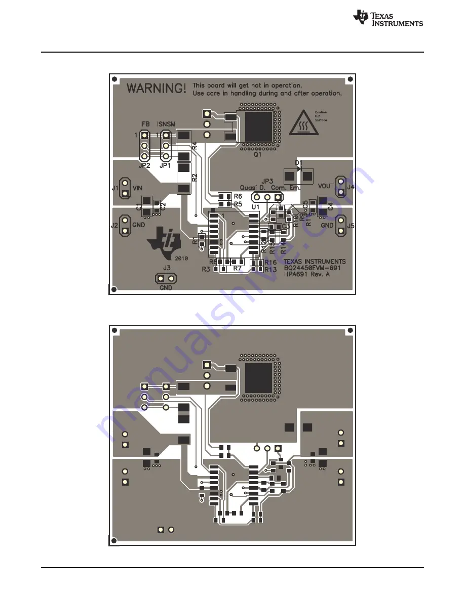
Board Layout
Figure 4. Top Assembly Layer
Figure 5. Top PCB Layer
8
bq24450EVM
SLUU464 – November 2010
Submit Documentation Feedback
© 2010, Texas Instruments Incorporated
Page 1: ...harge 4 4 2 Max Charge 4 4 3 Charge Termination 4 4 4 Re Charge 4 5 Functions and Features 5 5 1 Changing Output Voltage and Charge Current 5 5 2 Options for External Transistor 6 5 3 Other Options 6...
Page 2: ...ents limited only by the selection of the external pass transistor The versatile driver for the external pass transistor provides at least 25mA of base drive In addition to the voltage and current reg...
Page 3: ...2 3 Meters Three Fluke 75 DMMs equivalent or better 3 Equipment Setup The original test setup of HPA691 is shown in Figure 1 1 Set the PS 1 for 10V 1A current limit and then turn off supply Connect P...
Page 4: ...s is the pre charge current 4 2 Max Charge Adjust PS 2 such that VM 2 shows 6 VDC Using VM 3 measure the voltage across the current sense resistor on Load 1 Multiply this value by a conversion factor...
Page 5: ...on board resistors R7 R8 R9 R11 R12 See the bq24450 datasheet for information on how to size these resistors If Vout is changed Vin must also be changed Vin should be high enough to allow for the nece...
Page 6: ...JP3 such that it connects Pin 15 of the IC to the collector of Q1 2 Remove R6 and replace with Rp as calculated on page 13 of the data sheet 5 3 Other Options Disabling Pre Charge Mode The EVM is pop...
Page 7: ...pen Resistor Chip 1 16W 1 603 Std Std R15 R2 0 56 Resistor Chip 1 2W 1 2010 STD STD R3 R6 0 Resistor Chip 1 16W 603 Std Std R4 0 Resistor Chip 1 2W 2010 CRCW20100000Z0EF Vishay R7 475k Resistor Chip 1...
Page 8: ...ials Board Layouts and Schematic www ti com 7 2 Board Layout Figure 4 Top Assembly Layer Figure 5 Top PCB Layer 8 bq24450EVM SLUU464 November 2010 Submit Documentation Feedback 2010 Texas Instruments...
Page 9: ...l of Materials Board Layouts and Schematic Figure 6 Bottom PCB Layer 7 3 Schematic Figure 7 bq24450 EVM Schematic 9 SLUU464 November 2010 bq24450EVM Submit Documentation Feedback 2010 Texas Instrument...
Page 10: ...uct This notice contains important safety information about temperatures and voltages For additional information on TI s environmental and or safety programs please contact the TI application engineer...
Page 11: ...h statements TI products are not authorized for use in safety critical applications such as life support where a failure of the TI product would reasonably be expected to cause severe personal injury...