Board Layout
3-3
Physical Layouts
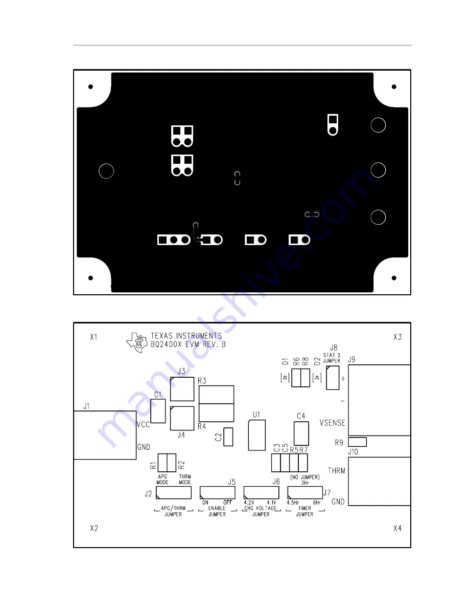
Figure 3–2. SLUP051 Board Layout Bottom Layer
Figure 3–3. SLUP051 Top Assembly View
Page 1: ...July 2002 Advanced Analog Products User s Guide SLUU083A...
Page 2: ...t that any license either express or implied is granted under any TI patent right copyright mask work right or other TI intellectual property right relating to any combination machine or process in wh...
Page 3: ...charger which delivers up to 1 2 A of continuous charge current for one or two cell applications How to Use This Manual This document contains the following chapters Chapter 1 Introduction Chapter 2...
Page 4: ...lications 2 2 2 2 2 For Two Cell Applications 2 3 3 Physical Layouts 3 1 3 1 Board Layout 3 2 4 Bill of Materials 4 1 4 1 Bill of Materials 4 2 4 2 bq2400x Charge Status Configurations 4 3 A Schematic...
Page 5: ...Li ion bq2400x charge management solution for one and two cell battery pack applications This guide describes a complete designed and tested charger which delivers up to 1 0 A of continu ous charge c...
Page 6: ...tage phase The user can configure the device for cells with either coke or graphite anodes Charge is terminated by either of the following methods Maximum time Minimum current detection 1 2 Performanc...
Page 7: ...m fault High TBATMAX J2 set to Therm 43 48 53 C Therm fault Low TBATMIN J2 set to Therm 0 5 10 C APG user defined see data sheet J2 set to APG Power dissipation PD VI VO Iload 2 3 W VI for a 2 cell sh...
Page 8: ...2 1 Test Summary Test Summary This chapter shows the test setups used and the tests performed in designing the bq2400xEVM Topic Page 2 1 Setup 2 2 2 2 Test Procedures 2 2 Chapter 2...
Page 9: ...pers on J4 J4 0 5 A charge use two jumpers placed horizontally no jumpers on J3 J2 Adapter power good APD or battery s thermistor J5 Enable on or off J6 Regulation voltage 4 2 V or 4 1 V single cell 8...
Page 10: ...ed in the 0 5 A charge mode by using a 7 3 W resistor in place of the battery Apply the resistor after the unit is powered If the battery discharges down to the HighV threshold the charger starts fast...
Page 11: ...fast charge mode until either the selected time expires or the battery charges to the selected regulation voltage The timeout feature is tested in the 0 5 A charge mode by using a 14 5 W resistor in p...
Page 12: ...3 1 Physical Layouts Physical Layouts This chapter contains the board layout and assembly drawings for the SLUP051 EVM Topic Page 3 1 Board Layout 3 2 Chapter 3...
Page 13: ...oard Layout 3 2 3 1 Board Layout Figure 3 1 shows the top layer of the SLUP051 Figure 3 2 shows the bottom layer Figure 3 3 shows the SLUP051 top assembly view Figure 3 1 SLUP051 Board Layout Top Laye...
Page 14: ...Board Layout 3 3 Physical Layouts Figure 3 2 SLUP051 Board Layout Bottom Layer Figure 3 3 SLUP051 Top Assembly View...
Page 15: ...als This chapter contains the bill of materials required for the SLUP051 EVM It also specifies the charge status configurations for the bq2400x Topic Page 4 1 Bill of Materials 4 2 4 2 bq2400x Charge...
Page 16: ...Pin strip header 2 pin 3M 1 J9 ED350 3 ED1610 ND Terminal block 3 pin On shore 1 R1 CR0805 105113F Resistor 51 1 k 1 1 10W see Note 1 Venkel 805 1 R2 CR0805 10W3163JT Resistor 316 1 1 10W see Note 1 V...
Page 17: ...ns for the bq2400x Table 4 2 Charge Status Configurations Part Number Number of Cells Charge Status Configuration bq24001 Single cell Single LED bq24002 Single cell 2 LED bq24003 Single cell Bicolor L...
Page 18: ...A 1 Schematic Schematic This chapter contains the schematic diagram for the EVM Topic Page A 1 Schematic A 2 Appendix A...
Page 19: ...G VSEL EN APG THM ISNS VCC N C N C IN IN N C OUT OUT N C VCC VCC VCC A2 B2 B1 A1 2 1 GRN C A RED C A 2 1 3 2 1 EN JUMPER APG THM JUMPER APG MODE THERMISTOR MODE STAT 2 JUMPER SCHEMATIC ON OFF 4 1V 4 2...