Texas Instruments BQ20Z40EVM-001 User Manual Download Page 9

7.1

Connecting the bq20z40/bq29330/bq29412 Circuit Module to a Battery Pack

+

-

LOAD/CHARGER

EV2300

COMPUTER

USB

SMBus

cable

+

-

SMB

7.2

PC Interface Connection

www.ti.com

Hardware Connection

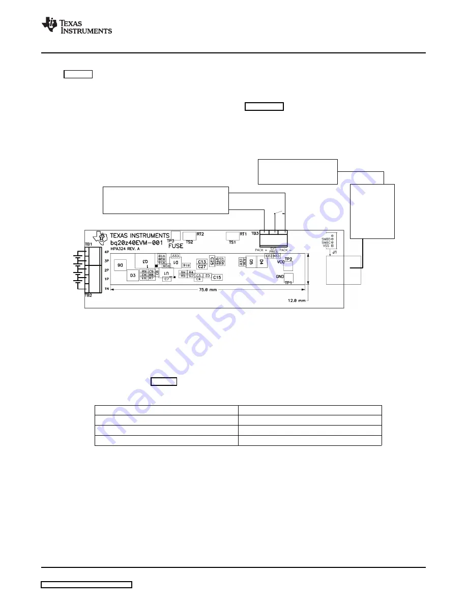
Figure 7

shows how to connect the bq20z40/bq29330/bq29412 circuit module to the cells and system

load/charger.

The cells must be connected in the following order:

1. 4-Cell Pack: 1N (BAT-), 1P, 2P, 3P, then 4P (see

Section 2.2

for definitions).

2. 3-Cell Pack: 1N (BAT-), 1P, 2P, and then connect 4P and 3P together.
3. 2-Cell Pack: 1N (BAT-), 1P, and then connect 4P, 3P, and 2P together

To start charge or discharge test, connect SYS PRES pin to PACK- pin to set SYS PRES state. To test
sleep mode, disconnect the SYS PRES pin.

Figure 7. bq20z40/bq29330 Circuit Module Connection to Cells and System Load/Charger

The following steps configure the hardware for interface to the PC:

1. Connect the bq20z40/bq29330-based smart battery to the EV2300 using the provided cable or the

connections shown in

Table 4

.

Table 4. Circuit Module to EV2300 Connections

bq20z40/bq29330-Based Battery

EV2300

SMBD

SMBD

SMBC

SMBC

VSS

GND

2. Connect the PC USB cable to the EV2300 and the PC USB port.

The bq20z40EVM-001 is now set up for operation.

SLUU320C – January 2009 – Revised June 2009

bq20z40EVM-001 SBS 1.1 Impedance Track™Technology

9

Enabled Battery Management Solution EVM

Submit Documentation Feedback

Summary of Contents for BQ20Z40EVM-001

Page 1: ...of the bq20z40 bq29330 bq29412 solution under different charge and discharge conditions Contents 1 Features 2 2 bq20z40 bq29330 Based Circuit Module 2 3 bq20z40 bq29330 Circuit Module Schematic 3 4 Ci...

Page 2: ...ll Any The bq20z40 bq29330 bq29412 based circuit module is a complete and compact example solution of a bq20z40 and bq29330 circuit for battery management and protection of Li ion or Li polymer packs...

Page 3: ...arge current path in order to sustain sufficient Pack voltage when the battery voltage is too low to power up the bq29330 IC If the charger has a precharge function R12 and FET Q2 are not used The EVM...

Page 4: ...ons PCB layers and assembly drawing for the bq20z40 bq29330 module Figure 1 bq20z40EVM 001 Layout Silk Screen Figure 2 Top Assembly Figure 3 Top Layer 4 bq20z40EVM 001 SBS 1 1 Impedance Track Technolo...

Page 5: ...youts and Bill of Materials Figure 4 Bottom Layer Figure 5 Bottom Assembly SLUU320C January 2009 Revised June 2009 bq20z40EVM 001 SBS 1 1 Impedance Track Technology 5 Enabled Battery Management Soluti...

Page 6: ...86 3 R13 R15 5 1K Resistor chip 5 1 k 1 16 W 5 0603 STD STD R18 3 R14 R25 1M Resistor chip 1 M 1 16 W 5 0603 STD STD R30 1 R16 100K Resistor chip 100 k 1 16 W 5 0603 STD STD 1 R17 0 010 75ppm Resistor...

Page 7: ...le Physical Layouts and Bill of Materials Figure 6 Schematic SLUU320C January 2009 Revised June 2009 bq20z40EVM 001 SBS 1 1 Impedance Track Technology 7 Enabled Battery Management Solution EVM Submit...

Page 8: ...tory Open the archive containing the installation package and copy its contents in a temporary directory The executable filename can consist of several component names and versions Double click on the...

Page 9: ...rge test connect SYS PRES pin to PACK pin to set SYS PRES state To test sleep mode disconnect the SYS PRES pin Figure 7 bq20z40 bq29330 Circuit Module Connection to Cells and System Load Charger The f...

Page 10: ...g check box is checked To disable the scan feature deselect Keep Scanning The continuous scanning period can be set via the Options and Set Scan Interval menu selections The range for this interval is...

Page 11: ...hat separates the Flags Static data from SBS values changes the height of the Flags Static Data display Selecting View then Auto Arrange returns the splitter bar to its original location The bq20z40 d...

Page 12: ...he bq20z40 using the Write All button The configuration information of the bq29330 and module calibration data is held in the bq20z40 data flash The bq20z40 allows for an automatic data flash export f...

Page 13: ...Calibration If Voltage Calibration is selected enter the number of cells on the pack If Temperature Calibration is selected select the sensor that is to be calibrated If the current source is connecte...

Page 14: ...Screen www ti com Figure 10 Calibration Screen 14 bq20z40EVM 001 SBS 1 1 Impedance Track Technology SLUU320C January 2009 Revised June 2009 Enabled Battery Management Solution EVM Submit Documentatio...

Page 15: ...valid values can cause erroneous results When scaling converted hex values to a higher number of bytes follow these rules When unsigned is selected the left pad contains zeroes When signed is selected...

Page 16: ...by its title and literature number Updated documents can also be obtained through the TI Web site at www ti com Documents Literature Number bq20z40 SBS 1 1 Compliant Gas Gauge With Impedance Track SLU...

Page 17: ...duct This notice contains important safety information about temperatures and voltages For additional information on TI s environmental and or safety programs please contact the TI application enginee...

Page 18: ...ce TI is not responsible or liable for any such statements TI products are not authorized for use in safety critical applications such as life support where a failure of the TI product would reasonabl...

Page 19: ...Mouser Electronics Authorized Distributor Click to View Pricing Inventory Delivery Lifecycle Information Texas Instruments BQ20Z40EVM 001...

Reviews: