


Software Examples
12
SLAU666B – June 2016 – Revised May 2018
Copyright © 2016–2018, Texas Instruments Incorporated
BOOSTXL-SENSORS Sensors BoosterPack Plug-in Module
3.1.2.3
Sensor Tiles
Four sensor tiles are available in the Sensor GUI for the
BoosterPack plug-in
module (see
). Each tile represents the data output for a sensor or set of integrated sensors. The
following is a brief description of each sensor tile:
The
OPT3001 Ambient Light Sensor
tile responds to ambient light, and displays the brightness of the
light in lux. Casting a shadow over this sensor causes the reading to decrease, and shining a light on the
sensor cause the reading to increase.
The
TMP007 IR Temperature Sensor
tile responds to infrared energy emitted by objects in its field of
view, displaying this in degrees Celsius. Holding a warm or cold object over the sensor causes a
response, even over short distances.
The
BME280 Ambient Temperature, Relative Humidity, and Atmospheric Pressure Sensor
tile
responds to atmospheric pressure in millimeters of mercury (which can be stimulated using a pressure
chamber or by lightly pressing on the sensor), relative humidity as a percentage, and ambient temperature
in degrees Celsius (both of which can be stimulated by breathing on the sensor).
The
IMU
tile is made up of two subtiles:
•
The
BMI160 Accelerometer and Gyroscope
tile responds to acceleration in g (which can be
stimulated by changing the orientation of the board with respect to Earth's gravity, by shaking, or by
changing speed along an axis) and rotation in degrees per second (which can be stimulated by rotating
the board about its axes).
•
The
BMM150 Magnetometer
tile responds to magnetic field in microtesla. This sensor can be
stimulated by changing the sensor orientation with respect to Earth's geomagnetic field or by passing a
magnet over it.
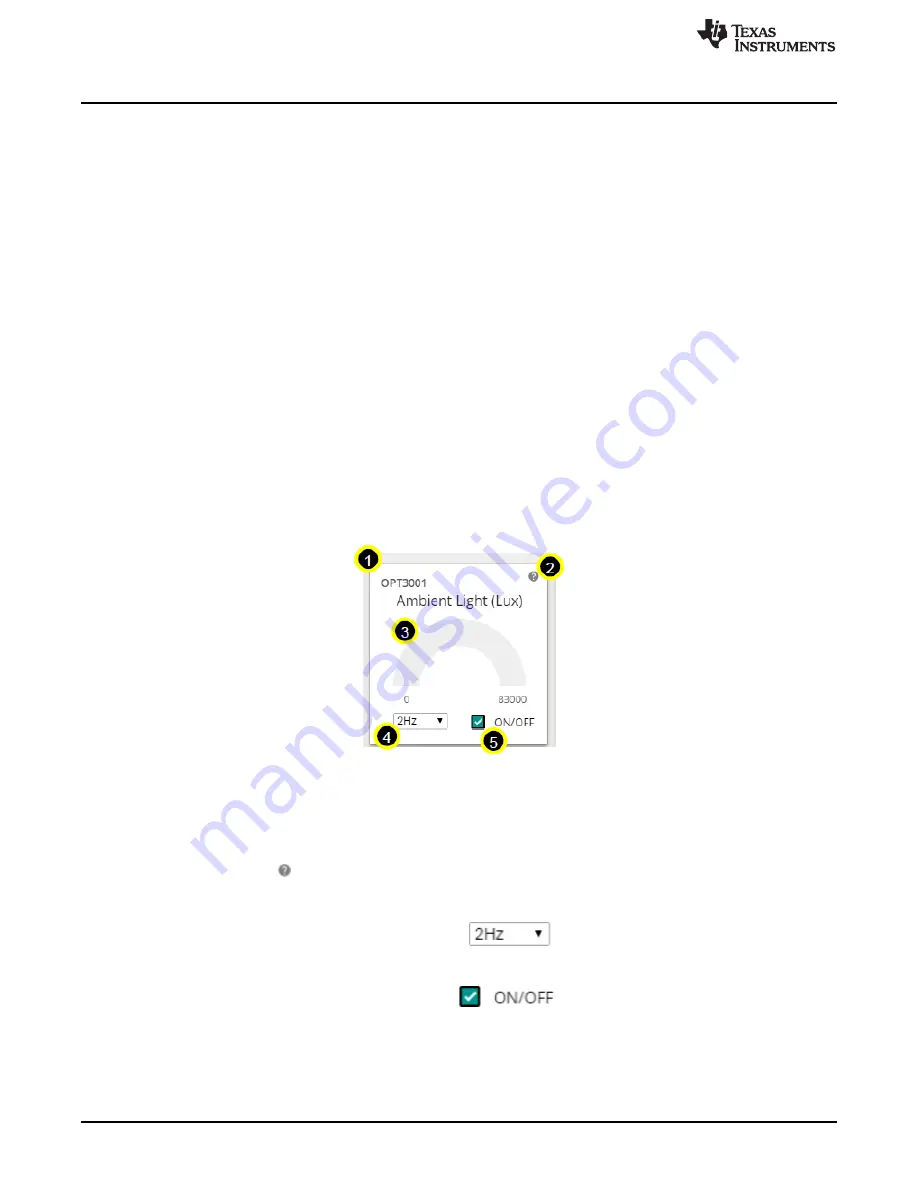
Figure 7. GUI Sensor Tile
The sensor tiles all share a common set of features. With a special case being the IMU (which consists of
the BMM150 and BMI160).
1. The sensor part number
2. A hint button. Click
for an animated demonstration on how to stimulate the sensors. Click again to
hide the hint.
3. A graphical and numerical read out of the sensor values.
4. A sample rate selection drop-down menu. Click
to select another frequency. This is the
frequency at which the sensor is checked, which also affects the rate at which the MCU wakes from
LPM0.
5. A button to toggle the sensor on and off. Click
to toggle the sensor on or off. The
current draw of each sensor's "ON" and "OFF" states can be seen in the table described in
, or in the
software hint.


