


www.ti.com
1.3
EVM Basic Functions
AMC7823 BLOCK
ADC
DAC 0
M
U
X
On-Chip
Temperature
Sensor
DAC 7
Reference
J1T
J1B
J5
P5
J2
P2
J4
P4
Control Signal
Control Signal
J3
1.25V
REF1
2.5V
REF2
J6
P6
POWER
TP1
W7
W1
R14
SGND
AGND
CH 0
CH 1
CH 2
CH 3
CH 4
CH 5
CH 6
CH 7
CH8
DAC0_OUT
DAC1_OUT
DAC2_OUT
DAC3_OUT
DAC4_OUT
DAC5_OUT
DAC6_OUT
DAC7_OUT
THERM _I_OUT
GPIO/DAV /GALR
GPIO/ALARM
W5
EVM Overview
The AMC7823 EVM is designed primarily as a functional evaluation platform to test certain functional
characteristics of the AMC7823 (analog monitoring and control circuit) converter. Functional evaluation of
the AMC7823 device can be accomplished with the use of any microprocessor or TI DSP with SPI
interface capability.
The headers J2 (top side) and P2 (bottom side) are pass through connectors provided for the control
signals and data required to interface a host processor to the AMC7823 EVM using a custom built cable.
The GPIO and alarm pins of the AMC7823 are also mapped to the J2 and J4 headers.
An adapter interface card (5-6k adapter interface) is also available to fit and mate with the TI C5000 and
C6000 DSP starter kit (DSK). This alleviates the troubles involved in building a custom cable. In addition,
there is also an MSP430 based platform (HPA449) that uses the MSP430F449 microprocessor, which this
EVM can connect to and interface with as well. For more details or information regarding the 5-6k adapter
interface card or the HPA449 platform, call Texas Instruments Inc. or email us at
.
The analog input signals for the ADC can be applied to the J1 and P1 pass through terminals differentially.
The analog inputs are decoupled to ground to eliminate the high frequency noise component that may be
present. In similar fashion, the DAC outputs can be monitored through the even pins of the J5 and P5
pass through header connectors.
The terminal connector, J3, is used for connecting an external component, such as a thermistor that can
be driven via the THERM_I_OUT pin. The current load can be precisely set by selecting the correct value
for R14. Refer to the data sheet for establishing the correct value for R14.
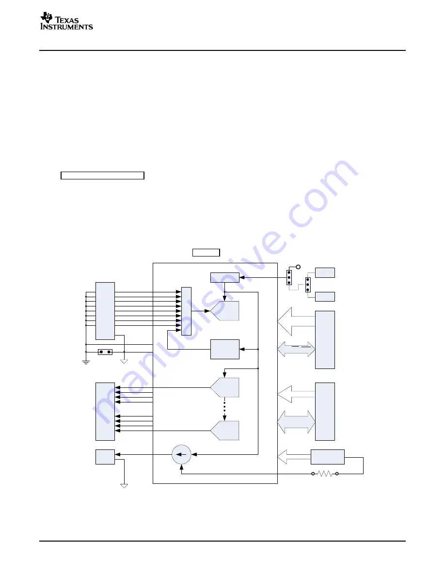
A block diagram of the EVM is shown in
Figure 1. EVM Block Diagram
SLAU171 – November 2005
AMC7823 Evaluation Module
3


