


4
Optional: Connect the camera module to the camera header of the
IDK, with the camera sensor facing away from the IDK.
Welcome to the AM571x Industrial Development Kit (IDK) Quick Start Guide. This guide is designed to
help you through the initial setup of the board. This IDK allows you to experience industrial applications
®
which showcase the AM571x’s Cortex -A15 and C66x processors, PRU-ICSS real-time industrial
communications subsystem and more. The AM571x IDK contains the following:
Default setup (OS boot from microSD card)
2
Connect the power cable to
the power jack on the board
and plug into an AC power
source.
Connect the supplied USB
Micro-B to Type-A cable to
the microUSB JTAG port J19
and plug the other end into
your PC/laptop USB port.
Then open a serial console
on your PC/laptop such as
Teraterm. This cable can also
be used for Code Composer
Studio (CCS) IDE control of
the IDK. Please see
for details
on CCS set up.
http://processors.wiki.ti.com/
index.php/Processor_SDK_
RTOS_Setup_CCS
3
1
Insert the µSD card into the
IDK. The µSD card will be
loaded with Processor SDK
RTOS when the kit is received.
The latest version of Processor
SDK RTOS and other software
compatible with the IDK can
be downloaded by visiting
www.ti.com/AM571xIDKSW
– 1 PCIe ×2 connector
– On-board XDS100 JTAG emulator
– On board USB serial port
– 20-pin JTAG connecter for external JTAG
emulator
•
Printed documents
– AM571x IDK Quick Start Guide (this
document)
– Terms and conditions
•
Miscellaneous
– µSD card with Processor SDK RTOS
– µSD-to-SD card adapter
– 1 micro USB 2.0 cable, 6 ft
µSD
Note:
When powering this IDK,
always use the supplied power
supply (GlobTek Part Number
TR9CA6500LCP-N, Model Number
GT-43008-3306-1.0-T3) or
equivalent model having output
voltage of +5VDC and output
current max 6.5 Amp as well as the
applicable regional product
regulatory/safety certification
requirements such as (by example)
UL, CSA, VDE, CCC, PSE, etc. The
power supply can be ordered on
eBay
http://www.ebay.com/
itm/-/291940638402
Camera header
5
Push the power on push
button (SW3) to run the IDK.
For more on out-of-box
diagnostics, please see:
www.ti.com/AM57xIDK-OOB
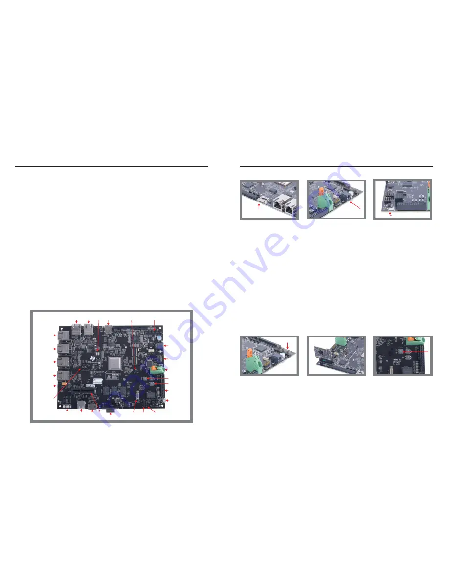
GIGETH0 GIGETH1
Status
LEDs
µSD
DCAN
header
HDMI PCIe
×2
USB1
USB2
Real-time
development
headers
PRU2ETH1
PRU2ETH0
PRU1ETH1
PRU1ETH0
Industrial LEDs
®
PROFIBUS
Haptics
RS-485
header
+5-V power
supply
20-pin JTAG
connector
USB JTAG/
serial console
PRU-ICSS I/O
and LEDs
Earth ground
connection
Hard reset
Power on
Camera
header
Enable for 4 PRU-ICSS
Ethernet Ports (J51)
USB JTAG/serial console
•
Hardware
– Sitara™ AM571x Cortex-A15 processor
– TPS6590377 power management I/C
– 10" capacitive touch LCD (sold separately as
TMDXIDK57X-LCD. A shunt needs to be
placed on J51 to enable LCD operation. See
PINMUX note.)
– 1GB DDR3 memory with ECC
– HDMI connector
– 256-Mb Quad SPI NOR Flash memory
– 16-GB eMMC memory
– USB1 High-Speed (USB2.0) host port
– USB2 High-Speed (USB2.0) host/device port
– 2 Gigabit Ethernet ports
– 2 10/100 Industrial Ethernet ports enabled by
default (All four 10/100 Industrial Ethernet
ports can be enabled by disabling the LCD
output by removing J51 shunt. See PINMUX
note.)
®
– 1 PROFIBUS port
– Haptics
– 6 Tricolor industrial and status LEDs
– 1 RS-485 port header
– 1 DCAN port header
PINMUX note for LCD and Ethernet ports:
Due to PINMUX, all six Ethernet ports cannot be used at the
same time that the LCD is used. The AM571x IDK is designed
to operate in two modes. The mode is chosen using a shunt on
header J51.
•
J51 shunt installed:
LCD and 4-port mode. LCD is enabled.
Ports GIGETH0, GIGETH1, PRU2ETH0, and PRU2ETH1 are
enabled. Ports PRU1ETH0 and PRU1ETH1 are disabled.
•
J51 shunt not installed:
6-port mode. LCD is disabled.
Ports GIGETH0, GIGETH1, PRU2ETH0, PRU2ETH1,
PRU1ETH0, and PRU1ETH1 are enabled.