Texas Instruments ADS8900BEVM-PDK User Manual Download Page 20

ADS8900BEVM-PDK Operation

www.ti.com

20

SBAU269 – October 2016

Submit Documentation Feedback

Copyright © 2016, Texas Instruments Incorporated

ADS8900BEVM-PDK

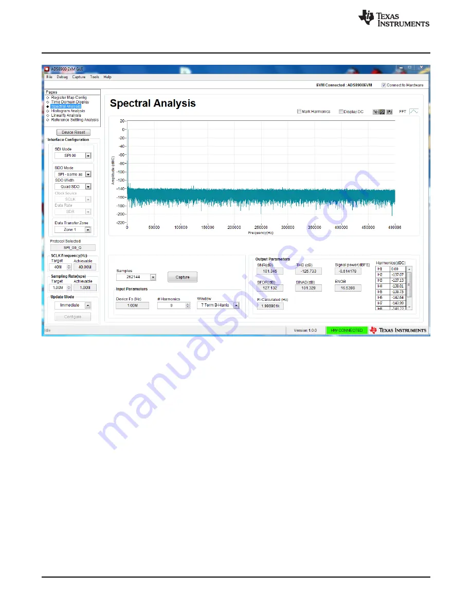
Figure 12. Spectral Analysis Tool

Finally, the FFT tool includes windowing options that are required to mitigate the effects of non-coherent
sampling (this discussion is beyond the scope of this document). The 7-Term Blackman Harris window is
the default option and has sufficient dynamic range to resolve the frequency components of up to a 24-bit
ADC. Note that the

None

option corresponds to not using a window (or using a rectangular window) and is

not recommended.

Summary of Contents for ADS8900BEVM-PDK

Page 1: ...ormance demonstration kit PDK This kit is an evaluation platform for the ADS8900B which is a 20 bit 1 MSPS fully differential input successive approximation register SAR analog to digital converter AD...

Page 2: ...of Materials PCB Layout and Schematics 25 7 1 Bill of Materials 25 7 2 PCB Layout 28 7 3 Schematics 31 List of Figures 1 OPA625 Differential Input Driving Path 6 2 Common Mode Selection Jumpers 7 3 AD...

Page 3: ...rated ADS8900BEVM PDK 1 J7 and J3 SMA Connectors Description 5 2 J4 and J6 Headers Description 5 3 J1 and J2 Configuration per Input Common Mode 7 4 External Source Requirements for Evaluation of the...

Page 4: ...B USB cable to connect to a computer 1 1 ADS8900BEVM PDK Features The ADS8900BEVM PDK includes the following features Hardware and software required for diagnostic testing as well as accurate perform...

Page 5: ...urce must be differential or balanced keeping the negative and positive inputs to the board symmetric such that Vs Vs at any given time Table 1 J7 and J3 SMA Connectors Description Pin Number Signal D...

Page 6: ...y the two OPA625 operational amplifiers drive the ADS8900B differential inputs with 2 2 impedance up to 7 MHz that properly drives the low dynamic impedance of the ADC inputs at 1 MSPS Figure 1 OPA625...

Page 7: ...up to the 1 k of the input resistor thereby moving the output common mode of the OPA625 amplifiers To compensate for this change in output common mode R1 can be modified according to the particular ex...

Page 8: ...ading conditions at full device throughput of 1 MSPS 3 Digital Interfaces As noted in Section 1 the EVM interfaces with the PHI that in turn communicates with the computer over USB There are two devic...

Page 9: ...d their loads to minimize inductance along the load current path 5 ADS8900BEVM PDK Initial Setup This section explains the initial hardware and software setup procedure that must be completed for the...

Page 10: ...opyright 2016 Texas Instruments Incorporated ADS8900BEVM PDK Figure 3 ADS8900B Software Installation Prompts As a part of the ADS8900BEVM GUI installation a prompt with a Device Driver Installation wi...

Page 11: ...8900BEVM PDK NOTE A notice may appear on the screen stating that Widows cannot verify the publisher of this driver software Select Install this driver software anyway The ADS8900BEVM PDK requires LabV...

Page 12: ...er 2016 Submit Documentation Feedback Copyright 2016 Texas Instruments Incorporated ADS8900BEVM PDK After these installations verify that C Program Files x86 Texas Instruments ADS8900BEVM is as shown...

Page 13: ...uter and evaluating the performance of the ADS8900B 1 Connect the ADS8900BEVM to the PHI Install the two screws as indicated in Figure 7 2 Use the USB cable provided to connect the PHI to the computer...

Page 14: ...n www ti com 14 SBAU269 October 2016 Submit Documentation Feedback Copyright 2016 Texas Instruments Incorporated ADS8900BEVM PDK 3 Launch the ADS8900BEVM GUI software as shown in Figure 8 Figure 8 Lau...

Page 15: ...tion options in this pane allow the user to choose from various SPI and multiSPI host interface options available on the ADS8900B The host always communicates with the ADS8900B using the standard SPI...

Page 16: ...le ADC sampling rate can differ from the target value depending on the applied SCLK frequency and selected Device Mode and the closest match achievable is displayed This pane therefore allows the user...

Page 17: ...lues on this page correspond to the Host Configuration Settings that enable ADC sampling at the maximum sampling rate specified for the ADC The register values can be edited by double clicking the cor...

Page 18: ...drive circuits The user can trigger a capture of the data of the selected number of samples from the ADS8900B as per the current interface mode settings using the capture button as indicated in Figur...

Page 19: ...d in Table 4 Table 4 External Source Requirements for Evaluation of the ADS8900B Specification Description Specification Value Signal frequency 2 kHz External source type Balanced differential Externa...

Page 20: ...includes windowing options that are required to mitigate the effects of non coherent sampling this discussion is beyond the scope of this document The 7 Term Blackman Harris window is the default opti...

Page 21: ...enerated by the various sources connected to the ADC when measuring a dc signal The cumulative effect of noise coupling to the ADC output from sources such as the input drive circuits the reference dr...

Page 22: ...d the external source must meet the requirements in Table 5 Table 5 External Source Requirements for ADS8900B Evaluation Specification Description Specification Value Signal frequency 2 kHz External s...

Page 23: ...e a low noise dc differential input to the ADC Set the parameters for the Reference Settling test The various test parameters are Samples This parameter defines the number of consecutive samples to be...

Page 24: ...ADS8900BEVM PDK Operation www ti com 24 SBAU269 October 2016 Submit Documentation Feedback Copyright 2016 Texas Instruments Incorporated ADS8900BEVM PDK Figure 15 Reference Settling Tool...

Page 25: ...C13 C39 C45 C50 C51 Murata CAP CERM 10 F 10 V 10 X7T 0603 GRM1885C1H102FA01J 3 C16 C31 C42 Murata CAP CERM 1000 pF 50 V 1 C0G NP0 0603 C2012X7S1A226M125AC 1 C20 TDK CAP CERM 22 F 10 V 20 X7S 0805 C080...

Page 26: ...ture SMT REF5050AIDGKT 1 U1 Texas Instruments Low Noise Very Low Drift Precision Voltage Reference 40 to 125 degC 8 pin VSSOP DGK Green RoHS no Sb Br TPS7A4700RGW 1 U2 Texas Instruments 36 V 1 A 4 17...

Page 27: ...0603 RG1608P 2491 B T5 0 R22 Susumu Co Ltd RES 2 49 k 0 1 0 1 W 0603 ERJ 3RQFR22V 0 R25 R26 Panasonic RES 0 22 ohm 1 0 1W 0603 RG1608P 303 B T5 0 R27 Susumu Co Ltd RES 30 0 k 0 1 0 1 W 0603 RG1608P 49...

Page 28: ...www ti com 28 SBAU269 October 2016 Submit Documentation Feedback Copyright 2016 Texas Instruments Incorporated ADS8900BEVM PDK 7 2 PCB Layout Figure 16 through Figure 19 illustrate the EVM PCB layout...

Page 29: ...com Bill of Materials PCB Layout and Schematics 29 SBAU269 October 2016 Submit Documentation Feedback Copyright 2016 Texas Instruments Incorporated ADS8900BEVM PDK Figure 17 ADS8900BEVM PCB Layer 2 GN...

Page 30: ...aterials PCB Layout and Schematics www ti com 30 SBAU269 October 2016 Submit Documentation Feedback Copyright 2016 Texas Instruments Incorporated ADS8900BEVM PDK Figure 18 ADS8900BEVM PCB Layer 3 Powe...

Page 31: ...chematics 31 SBAU269 October 2016 Submit Documentation Feedback Copyright 2016 Texas Instruments Incorporated ADS8900BEVM PDK Figure 19 ADS8900BEVM PCB Layer 4 Bottom Layer 7 3 Schematics Figure 20 th...

Page 32: ...C35 AGND AGND 1 2 3 J6 TSM 103 01 L SV AGND 1 F C36 AGND 0 R52 5 2V 1 F C40 AGND 1 F C38 AGND EVM_DVDD REF_BUF 0 01 F C34 AGND 0 01 F C37 10 F C28 DNP 10 F C29 DNP 10 F C27 DNP 10 F C24 DNP AGND AGND...

Page 33: ...P AGND 1 F 0603 C5 AGND AGND 47 F C3 AGND 5 2V 0 1 R2 AGND 1 F C2 AGND 5 2V 0 22 R8 10 F C4 AGND 5016 TP4 REFOUT 10 0k R5 20 0k R15 20 0k R10 AGND J2 87898 0204 AGND J1 87898 0204 280k R1 1 F C6 AGND...

Page 34: ...Logo3 FCC disclaimer Rafael Ordonez H5 1891 H8 1891 H6 1891 H7 1891 H1 PMSSS 440 0025 PH H2 PMSSS 440 0025 PH H3 PMSSS 440 0025 PH H4 PMSSS 440 0025 PH LOGO PCB Logo2 Texas Instruments Label Assembly...

Page 35: ...are returned during the warranty period to the address designated by TI and that are determined by TI not to conform to such warranty If TI elects to repair or replace such EVM TI shall have a reasona...

Page 36: ...transmitter has been approved by Industry Canada to operate with the antenna types listed in the user guide with the maximum permissible gain and required antenna impedance for each antenna type indic...

Page 37: ...ified allowable ranges some circuit components may have elevated case temperatures These components include but are not limited to linear regulators switching transistors pass transistors current sens...

Page 38: ...REMOVAL OR REINSTALLATION ANCILLARY COSTS TO THE PROCUREMENT OF SUBSTITUTE GOODS OR SERVICES RETESTING OUTSIDE COMPUTER TIME LABOR COSTS LOSS OF GOODWILL LOSS OF PROFITS LOSS OF SAVINGS LOSS OF USE L...

Page 39: ...sponsible for compliance with all legal regulatory and safety related requirements concerning its products and any use of TI components in its applications notwithstanding any applications related inf...

Reviews: