


6 ADS8568EVM Operation
The following instructions are a step-by-step guide to connecting the ADS8568EVM to the computer and
evaluating the performance of the ADS8568:
6.1 Connecting the Hardware and Running the GUI
1. Set the jumpers according to
.
2. Physically connect P2 of the PHI to J10 of the ADS8568EVM. Install the screws to assure a robust
connection.
3. Connect USB on PHI to the computer first.
a. LED D5 on the PHI lights up, indicating that the PHI is powered up.
b. LEDs D1 and D2 on the PHI start blinking to indicate that the PHI is booted up and communicating with
shows the resulting LED indicators.
4. Start the software GUI as shown in
. You will notice that the LEDs blink slowly as the FPGA
firmware is loaded on the PHI. This will take a few seconds then the AVDD and DVDD power supplies will
turn on.
5. Connect the high voltage power supplies (HVDD = +15 V, HVSS = -15 V, and GND).
6. Connect the signal generator. The default input range is ±10 V (or 10Vpk). A common input signal applied is
a sinusoidal 1kHz, 9.9Vpk signal with a 0 V offset. Note that this signal is adjusted just below the full scale
range to avoid clipping.
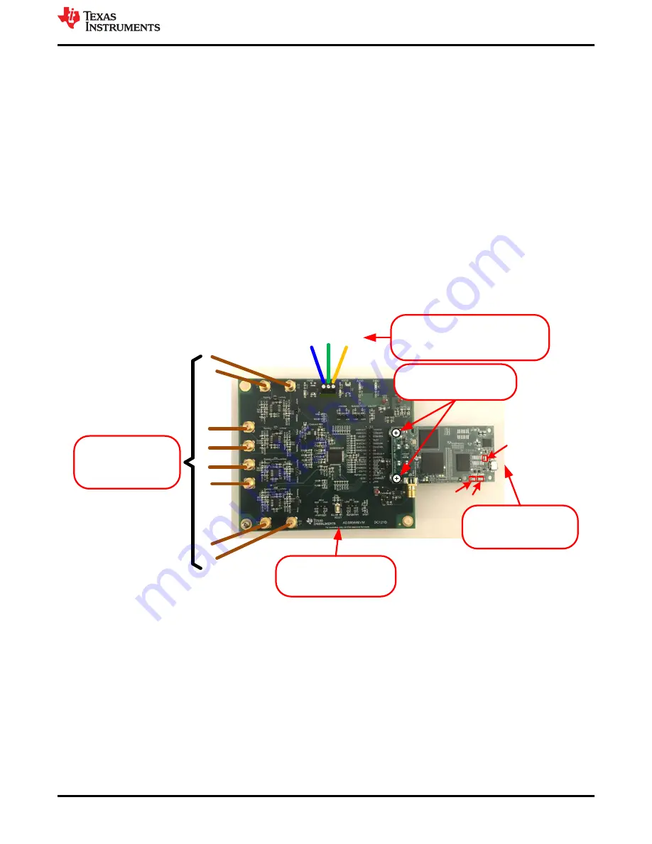
3. Connect USB power before
applying signal source.
4. Start the software GUI.
1. Set jumpers according to
your requirements. Review
Table 6-1 for details.
6. Apply input signals.
Input range = ±10V in the
default configuration.
Connect the eight input
channels as desired.
D5
D1
D2
2. Connect PHI to ADS8568EVM
and install screws.
ADS8568EVM
PHI
H
V
S
S
G
N
D
H
V
D
D
HVSS
-15V
GND
HVDD
+15V
5. Apply high voltage power supplies using
external DC lab supply (not provided).
HVDD = +15V, HVSS = -15V, and GND = 0V.
Figure 6-1. ADS8568EVM Hardware Setup and LED Indicators
ADS8568EVM Operation
SBAU193E – JUNE 2011 – REVISED MAY 2021
ADS8568EVM-PDK Evaluation Module
13
Copyright © 2021 Texas Instruments Incorporated