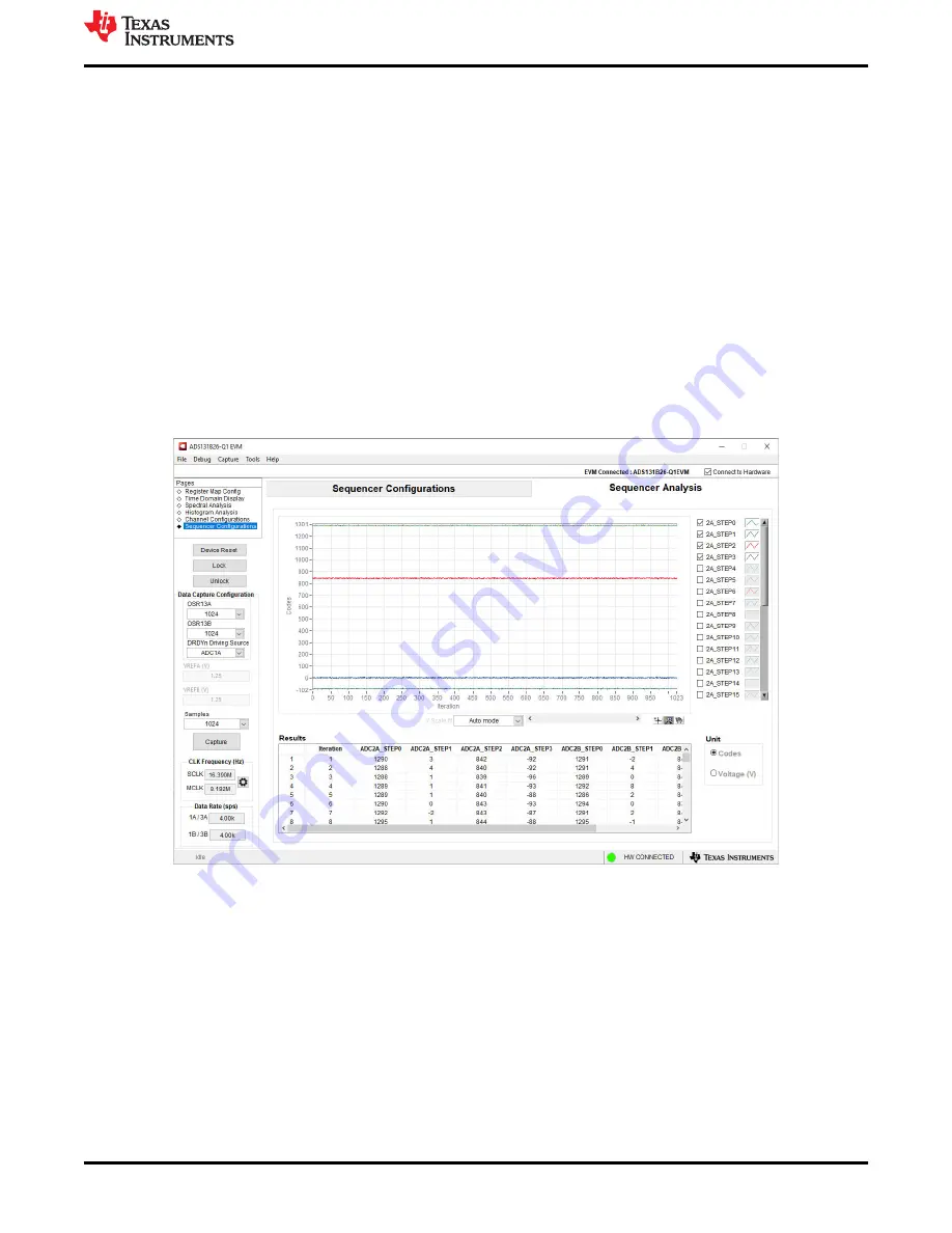
6.3.4 Sequencer Analysis
The
Sequencer Analysis
tool displays the raw ADC conversion data for ADC2A and ADC2B. This tool can be
accessed by selecting the
Sequencer Configurations
page from the top-left side of the GUI window. This page
defaults to the
Sequencer Configurations
. When the sequencer steps are enabled
and configured, select the right tab at the top of the window to access the
Sequencer Analysis
display.
From the
Sequencer Analysis
page, initiate a data capture by specifying the desired number of sequencer
iterations in the
Samples
drop-down menu and clicking the
Capture
button on the left side of the window.
This button collects the specified number of samples from each sequencer step that is enabled. The GUI
uses Sequencer Mode 01b, which initiates a new sequence of measurements after each DRDYn falling edge.
For demonstration purposes, the GUI configures ADC1A and ADC1B to use the highest OSR setting, which
produces the minimum data rate and allows the maximum time for each sequence to complete.
The sequencer results are plotted by the
Iteration
number on the x-axis of the graph. Each enabled sequence
step is automatically enabled for display, but the user can deselect any plot by unchecking the box next to
the sequence step in the legend on the right side. Below the plot is a
Results
summary table, which lists the
results from each step and each sequence iteration. The results in the plot and summary table can be displayed
in either
Codes
or
Voltage (V)
by using the radio buttons on the bottom-right.
sequencer data capture.
Figure 6-8. Sequencer Analysis Tool
ADS131B26Q1EVM-PDK Software Reference
SBAU413 – OCTOBER 2022
ADS131B26Q1EVM-PDK Evaluation Module
23
Copyright © 2022 Texas Instruments Incorporated


