Using the ADS1178EVM-PDK/ADS1278EVM-PDK Plug-in ADCPro
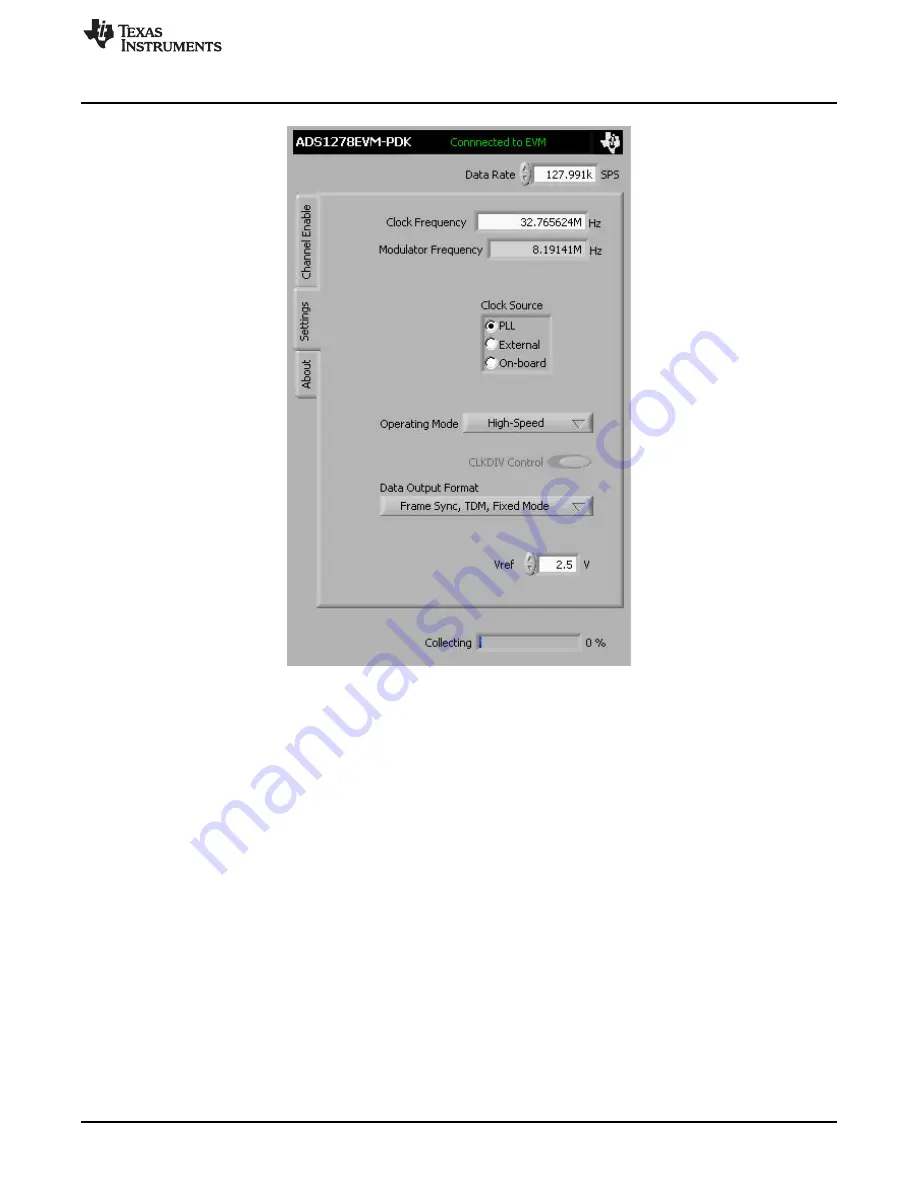
Figure 3. Clock Settings and Mode
The Clock Source control selects the input clock source for the ADS1278. The clock can be selected
from the MMB0 PLL, an External source, or use the On-board oscillator.
The Modulator Frequency indicator shows the ADS1278 modulator frequency based on the clock
source.
The Clock Frequency control allows the user to input the desired clock frequency when the PLL clock
source is selected. Once the frequency is entered, the software finds the closest frequency for the PLL to
synthesize (and which is within the maximum allowable frequency for the mode selected). This clock
frequency is configured in the PLL and overwrites the user entered value in the Clock Frequency
indicator.
The Operating Mode control allows selection of the converter operating mode: High-Speed,
High-Resolution, Low-Power, or Low-Speed.
The CLKDIV control can be set to 0 or 1.
The Data Output Format allows selection of the data output formats. For the ADS1278EVM software, the
formats are limited to the Frame Sync, TDM Format. The available options select whether the software
collects data for all channels Fixed Mode or only channels that are powered up Dynamic Mode.
The Vref control allows the user to input the current Vref value being used by the data converter. This
control does not change the actual reference voltage, but is required for the software to process the data
correctly for display.
The maximum clock frequency is shown for the different converter options in
9
SBAU197
–
February 2012
ADS1x7xEVM-PDK
Copyright
©
2012, Texas Instruments Incorporated


