Texas Instruments ADC32RF-EVM Series User Manual Download Page 9

www.ti.com

Quick-Start Procedure for Bypass LMFS82820 Mode in ADC32RF45

9

SLAU620D – April 2016 – Revised August 2017

Submit Documentation Feedback

Copyright © 2016–2017, Texas Instruments Incorporated

ADC32RFxx-EVM

3

Quick-Start Procedure for Bypass LMFS82820 Mode in ADC32RF45

This mode is available only in the ADC32RF4x family and is not available in ADC32RF8x family of
devices. Please check the package marking on the ADC to confirm compatibility of the device mounted on
the EVM with this mode.

3.1

TSW14J56

1. Connect the ADC32RFxx EVM to the TSW14J56 using the FMC connectors.

2. Connect a 5-V power supply to connector J11 (+5V IN).

3. Connect a USB cable to the USB connector (J9).

4. Flip the power switch (SW6) to the “ON” position.

3.2

ADC32RFxx EVM

1. Verify the clocking selection jumper JP3 is set to EXT for external clocking.

2. Connect a 5-V, 3-A power supply to connector J15. Do not use a supply that is rated less than 3 A.

3. Connect a USB cable to the USB connector (J11 bottom side of board).

4. Connect an analog RF signal from the signal source to the AINP SMA (J2).

5. Connect a signal generator set for 2.94912 GHz to the external clock input J5.

6. Connect another signal generator set for 2.94912 GHz to the LMK04828 reference clock input J7.

(Make sure the two signal generators for the ADC clock and LMK04828 clock are synchronized to the
same timebase, or use a single signal generator and a splitter to generate two copies of the clock to go
to the EVM.)

Fs = 2.94912 GHz, 5-Sample Example

This example captures data from channel A of the ADC32RFxx EVM sampling at 2.94912 GHz with a
1900-MHz input source. The ADC requires the device clock and SYSREF signals to be present

before

the

ADC can be properly configured. The steps to configure into this mode follow:

1. Open the ADC32RFxx EVM GUI.

2. Verify that the green

USB Status

indicator is lit. If it is not lit, click the

Reconnect?

button and check

the

USB Status

indicator again. If it is still not lit then verify the EVM is connected to the computer

through USB. Whenever the USB link is disturbed, the GUI must obtain a new handle to address the
proper USB port, and the

Reconnect?

button does that.

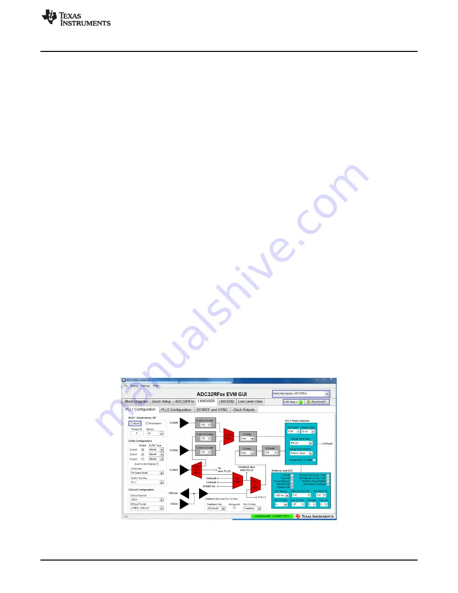
3. On the PLL1 tab of the LMK04828 tab, press the

RESET

button.

Figure 3. ADC32RFxx-EVM GUI LMK04828 PLL1 Page Bypass Mode

4. On the ADC32RFxx-EVM, press SW1 (

ADC RESET

) to provide a hardware reset to the ADC.

Summary of Contents for ADC32RF-EVM Series

Page 1: ... Quick Start Procedure for Bypass LMFS82820 Mode in ADC32RF45 9 3 1 TSW14J56 9 3 2 ADC32RFxx EVM 9 3 3 High Speed Data Converter Pro HSDC Pro 11 4 Quick Start Procedure for Digital DDC Decimation Plus NCO Mode in ADC32RF82 13 4 1 TSW14J56 13 4 2 ADC32RF82 EVM 13 4 3 High Speed Data Converter Pro HSDC Pro 18 5 Quick Start Procedure for Digital DDC Decimation Plus NCO Mode in ADC32RF4x and ADC32RF8x...

Page 2: ...ick Setup View Bypass Mode 30 29 HSDC Pro Device Selection LMFS_8224 Mode 31 30 Example Capture from Channel A LMFS8224 Mode 31 31 ADC32RF42 EVM Quick Setup View Bypass Mode 33 32 HSDC Pro Device Selection LMFS_42810 Mode 34 33 Example Capture from Channel A LMFS42810 Mode 35 34 ADC32RFxx EVM GUI With LMX Clock Configuration 36 35 ADC32RFxx EVM GUI With LMK Clock Configuration 37 Trademarks Micros...

Page 3: ...VM data capture board two 5 V power supplies and mini USB cable Computer running Microsoft Windows XP or newer One low noise signal generator Recommendations RF generator 17 dBm 40 dBc harmonics 500 fs jitter 20 kHz 20 MHz 10 MHz to 3 GHz frequency range Examples HP HP8644B Rohde Schwarz SMA100A Bandpass filter for desired analog input Recommendations Bandpass filter 60 dB harmonic attenuation 5 b...

Page 4: ...Overview www ti com 4 SLAU620D April 2016 Revised August 2017 Submit Documentation Feedback Copyright 2016 2017 Texas Instruments Incorporated ADC32RFxx EVM Figure 1 EVM Feature Locations ...

Page 5: ...page www ti com product ADC32RF45 ADC32RF44 data sheet SBAS809 ADC32RF44 product page www ti com product ADC32RF44 ADC32RF8x data sheet SBAS774 ADC32RF80 product page www ti com product ADC32RF80 LMK04828 data sheet SNAS605 TSW14J56EVM User s Guide SLWU086 High Speed Data Converter Pro software SLWC107 and User s Guide SLWU087 available at www ti com tool dataconverterpro sw HSDC Pro GUI Updates S...

Page 6: ...sic configurations TI strongly suggests setting up the EVM and capture card with a configuration described in this document and getting a working setup before modifying the configuration to be closer to what the end application requires In this way the user can know that the hardware is functioning and that there is a working configuration that they can go back to in the event of difficulty develo...

Page 7: ...staller is completed the executable is located at C Program Files 86 Texas Instruments ADC32RFxx EVM GUI 5 Start the GUI by double clicking on ADC32RFxx EVM GUI exe or Start Menu All Programs Texas Instruments ADC32RFxxGUI 6 When plugging the board into the computer for the first time through the USB cable you may be prompted to install the USB drivers Windows XP If Windows XP does not automatical...

Page 8: ...2 MHz Bandpass Filter 1900 MHz Bandpass Filter AINP Low Noise Power Supply 5 VDC at 3 A Quick Start Guide www ti com 8 SLAU620D April 2016 Revised August 2017 Submit Documentation Feedback Copyright 2016 2017 Texas Instruments Incorporated ADC32RFxx EVM 2 3 Hardware Setup Procedure A typical test setup using the ADC32RFxx EVM and TSW14J56EVM is shown in Figure 2 This is the test setup used for the...

Page 9: ... a signal generator set for 2 94912 GHz to the external clock input J5 6 Connect another signal generator set for 2 94912 GHz to the LMK04828 reference clock input J7 Make sure the two signal generators for the ADC clock and LMK04828 clock are synchronized to the same timebase or use a single signal generator and a splitter to generate two copies of the clock to go to the EVM Fs 2 94912 GHz 5 Samp...

Page 10: ... EVM 5 Click on the Quick Setup tab 6 Select the Nyquist Zone for the input It will be 2nd Nyquist in this example setup Fs 2949 12M Fin 1900M Figure 4 ADC32RFxx EVM Quick Setup View Bypass Mode 7 Select the Clock Source to ADC In this example External Clocking is selected 8 Select ADC32RF45 Mode In this example Bypass is chosen 9 Select Resolution In this example 12 bit is selected 10 Press PROGR...

Page 11: ...gure 5 ADC32RFxx EVM GUI JESD204B Tab Bypass Mode 3 3 High Speed Data Converter Pro HSDC Pro 1 Open High Speed Data Converter Pro v4 5 or newer by going to Start Menu All Programs Texas Instruments High Speed Data Converter Pro 2 Click OK to connect to the TSW14J56 If there is more than one TSW14J56 connected to the host PC select the appropriate serial number of the board to be programmed 3 Selec...

Page 12: ...ad to the TSW14J56 6 After the firmware download has completed enter 2949 12M into the ADC Output Data Rate field at the bottom left corner of the HSDC Pro GUI 7 Select Channel 1 2 in the channel select window located at the top middle of the GUI 8 Click the Instrument Options menu at the top of HSDC Pro and select Reset Board 9 Click the Capture button in HSDC Pro to capture data from the ADC 10 ...

Page 13: ...ignal generator set at 2 GHz to the external clock input J5 6 Connect another signal generator set for 2 GHz to the LMK04828 reference clock input J7 Make sure the two signal generators for the ADC clock and LMK04828 clock are synchronized to the same timebase or use a single signal generator and a splitter to generate two copies of the clock to go to the EVM Fs 2 GHz 8x Decimation Example Externa...

Page 14: ...16 2017 Texas Instruments Incorporated ADC32RFxx EVM Figure 8 ADC32RFxx EVM GUI LMK04828 PLL1 Page DDC Mode 3 On the LMK04828 PLL1 tab press the RESET button 4 On the ADC32RFxx EVM press SW1 ADC RESET to provide a hardware reset to the ADC 5 Click on the Quick Setup tab 6 Select the Nyquist Zone for the input It will be 2nd Nyquist in this example setup Fs 2000M Fin 1860M ...

Page 15: ...August 2017 Submit Documentation Feedback Copyright 2016 2017 Texas Instruments Incorporated ADC32RFxx EVM Figure 9 ADC32RFxx EVM Quick Setup View DDC Mode 7 Select the Clock Source to ADC In this example External Clocking is selected 8 Select ADC32RF45 Mode In this example DDC is chosen 9 Press the PROGRAM EVM button ...

Page 16: ...0D April 2016 Revised August 2017 Submit Documentation Feedback Copyright 2016 2017 Texas Instruments Incorporated ADC32RFxx EVM 10 After pressing the PROGRAM EVM button the device will be configured as shown in Figure 9 and Figure 10 Figure 10 ADC32RFxx EVM GUI JESD204B Configuration Tab DDC Mode ...

Page 17: ... box for the Channel A DDC0 NCO1 frequency The control value for NCO1 should become 60621 as shown in Figure 11 NOTE These settings only apply with Fs 2000 MHz The NCOs in the ADC32RFxx are set to a desired LO frequency by a numeric control that is a fraction of the sampling frequency If the sampling frequency changes then the NCO frequency changes In order to find the input tone in the resulting ...

Page 18: ...appropriate serial number of the board to be programmed Figure 12 Connecting to TSW14J56 3 Select the ADC tab at the top of the GUI 4 Use the Select ADC drop down menu at the top left corner to select ADC32RF80_LMF_8821 as Figure 13 shows Figure 13 HSDC Pro Device Selection LMFS8821 Mode 5 When prompted to update the firmware for the ADC click Yes and wait for the firmware to download to the TSW14...

Page 19: ...t window located at the top middle of the GUI 8 Click the Instrument Options menu at the top of HSDC Pro and select Reset Board Figure 15 Resetting the TSW14J56 9 Click Capture in HSDC Pro to capture data from the ADC 10 Select Complex FFT 11 The result should match the example capture in Figure 17 The input tone is seen to be near 10 MHz because the signal generator is set to 1 86 GHz while the N...

Page 20: ...imation Plus NCO Mode in ADC32RF82 www ti com 20 SLAU620D April 2016 Revised August 2017 Submit Documentation Feedback Copyright 2016 2017 Texas Instruments Incorporated ADC32RFxx EVM Figure 17 Example Capture From Channel A 8x Decimation Mode ...

Page 21: ...able to the USB connector J11 on the bottom side of board 4 Connect an analog RF signal from a signal source to the AINP SMA J2 5 Connect a signal generator set for 2 94912 GHz to the external clock input J5 6 Connect another signal generator set for 2 94912 GHz to the LMK04828 reference clock input J7 Make sure the two signal generators for the ADC clock and LMK04828 clock are synchronized to the...

Page 22: ...ht 2016 2017 Texas Instruments Incorporated ADC32RFxx EVM Figure 18 ADC32RFxx EVM GUI LMK04828 PLL1 Page DDC Mode 3 On the LMK04828 PLL1 tab press the RESET button 4 On the ADC32RFxx EVM press SW1 ADC RESET to provide a hardware reset to the ADC 5 Click on the Quick Setup tab 6 Select the Nyquist Zone for the input It will be 2nd Nyquist in this example setup Fs 2949 12M Fin 1960M ...

Page 23: ...evised August 2017 Submit Documentation Feedback Copyright 2016 2017 Texas Instruments Incorporated ADC32RFxx EVM Figure 19 ADC32RFxx EVM Quick Setup View DDC Mode 7 Select the Clock Source to ADC In this example External Clocking is selected 8 Select ADC32RF45 Mode In this example DDC is chosen 9 Press the PROGRAM EVM button ...

Page 24: ...d August 2017 Submit Documentation Feedback Copyright 2016 2017 Texas Instruments Incorporated ADC32RFxx EVM 10 After pressing the PROGRAM EVM button the device is configured as shown in Figure 19 and Figure 20 indicating the 12 bit packed 5 sample mode for LMFS82820 Figure 20 ADC32RFxx EVM GUI JESD204B Configuration Tab DDC Mode ...

Page 25: ... in the box for the Channel A DDC0 NCO1 frequency The control value for NCO1 should become 42222 as shown in Figure 21 NOTE These settings only apply with Fs 2 94912 GHz The NCOs in the ADC32RF80 are set to a desired LO frequency by a numeric control that is a fraction of the sampling frequency If the sampling frequency changes then the NCO frequency changes In order to find the input tone in the ...

Page 26: ...ect the appropriate serial number of the board to be programmed Figure 22 Connecting to TSW14J56 3 Select the ADC tab at the top of the GUI 4 Use the Select ADC drop down menu at the top left corner to select ADC32RF80_LMF_8821 as Figure 23 shows Figure 23 HSDC Pro Device Selection LMFS8821 Mode 5 When prompted to update the firmware for the ADC click Yes and wait for the firmware to download to t...

Page 27: ...hannel select window located at the top middle of the GUI 8 Click the Instrument Options menu at the top of HSDC Pro and select Reset Board Figure 25 Resetting the TSW14J56 9 Click Capture in HSDC Pro to capture data from the ADC 10 Select Complex FFT 11 The result should match the example capture in Figure 27 The input tone is seen to be near 60 MHz because the signal generator is set to 1 96 GHz...

Page 28: ... Plus NCO Mode in ADC32RF4x and ADC32RF8x www ti com 28 SLAU620D April 2016 Revised August 2017 Submit Documentation Feedback Copyright 2016 2017 Texas Instruments Incorporated ADC32RFxx EVM Figure 27 Example Capture From Channel A 8x Decimation Mode ...

Page 29: ...er Fs 2 4576 GHz LMFS 8224 Example This example captures data from channel A of the ADC32RF44 EVM sampling at 2 4576 GHz with a 1800 MHz input source The ADC requires the device clock and SYSREF signals to be present before the ADC can be properly configured Use the following steps to configure into this mode 1 Open the ADC32RFxx EVM GUI 2 Verify that the green USB Status indicator is lit If it is...

Page 30: ...ure 28 ADC32RF44 EVM Quick Setup View Bypass Mode 7 Select the Clock Source to ADC In this example LMX2582 is used to Clock the ADC 8 Select the Internal Clk Freq In this example 2457 6 Msps is selected 9 Select ADC32RF45 Mode In this example Bypass is chosen 10 Select Resolution In this example 14 bit is selected 11 Press PROGRAM EVM 12 After pressing the PROGRAM EVM button the device will be con...

Page 31: ... Select the ADC tab at the top of the GUI 4 Use the Select ADC drop down menu at the top left corner to select ADC32RF45_LMF_8224 Figure 29 HSDC Pro Device Selection LMFS_8224 Mode 5 When prompted to update the firmware for the ADC click Yes and wait for the firmware to download to the TSW14J56 6 After the firmware download has completed enter 2949 12M into the ADC Output Data Rate field at the bo...

Page 32: ...16 being reported by the GUI when it is really decimation by 8 when the ADC32RF42 is being used The configuration files supplied with the GUI for the ADC32RF42 already take this difference in decimation factor into account 7 1 TSW14J56 Follow the steps listed in Section 3 1 7 2 ADC32RF42 EVM Follow the steps listed in Section 3 2 with the exception of steps 5 and 6 Instead of supplying an external...

Page 33: ...xample 1536 Msps is selected Upon first launch of the GUI the default clock rate selection may be grayed out if the clock rate is too fast or too slow for the ADC If the GUI comes up with a grayed out selection then a valid selection must be chosen before pressing PROGRAM EVM else an error message will pop up saying that a config file for this clock rate could not be found 9 Select ADC32RF45 Mode ...

Page 34: ...down menu at the top left corner to select ADC32RF45_LMF_42810 If this device selection is not available a newer version of HSDCPro may need to be downloaded or a device ini file for the mode may be obtained from TI and copied into the HSDCPro installation Figure 32 HSDC Pro Device Selection LMFS_42810 Mode 5 When prompted to update the firmware for the ADC click Yes and wait for the firmware to d...

Page 35: ...LMFS 42810 Mode in ADC32RF42 With Internal Clocking 35 SLAU620D April 2016 Revised August 2017 Submit Documentation Feedback Copyright 2016 2017 Texas Instruments Incorporated ADC32RFxx EVM Figure 33 Example Capture from Channel A LMFS42810 Mode ...

Page 36: ...clock to the ADC to be generated on the EVM either by the LMX2582 or the LMK04828 The default configuration for the EVM is for the LMX2582 to be the clock source to the ADC while in internal clock mode To select the LMK04828 as the ADC clock source there are two AC coupling caps to unsolder and resolder in a different position There need not be any input to the J5 external clock SMA If the LMK0482...

Page 37: ...410 and solder them into positions C431 and C432 This disconnects the ADC device clock from the LMX2582 outputs and instead connects the LMK04828 device clock output to be the clock source to the ADC There need not be any input to the J5 external clock SMA If the LMK04828 is to be synchronized to the timebase of the signal generator used for the analog input then connect the 10 MHz sync signal fro...

Page 38: ...orporated Revision History Revision History NOTE Page numbers for previous revisions may differ from page numbers in the current version Changes from C Revision May 2017 to D Revision Page Added ADC32RF82 to list of supported devices in the abstract 1 Added Quick Start Procedure for Digital DDC Decimation Plus NCO Mode in ADC32RF82 section 13 ...

Page 39: ...y set forth above or credit User s account for such EVM TI s liability under this warranty shall be limited to EVMs that are returned during the warranty period to the address designated by TI and that are determined by TI not to conform to such warranty If TI elects to repair or replace such EVM TI shall have a reasonable time to repair such EVM or provide replacements Repaired EVMs shall be warr...

Page 40: ...the user guide with the maximum permissible gain and required antenna impedance for each antenna type indicated Antenna types not included in this list having a gain greater than the maximum gain indicated for that type are strictly prohibited for use with this device Concernant les EVMs avec antennes détachables Conformément à la réglementation d Industrie Canada le présent émetteur radio peut fo...

Page 41: ...ed loads Any loads applied outside of the specified output range may also result in unintended and or inaccurate operation and or possible permanent damage to the EVM and or interface electronics Please consult the EVM user guide prior to connecting any load to the EVM output If there is uncertainty as to the load specification please contact a TI field representative During normal operation even ...

Page 42: ...COST OF REMOVAL OR REINSTALLATION ANCILLARY COSTS TO THE PROCUREMENT OF SUBSTITUTE GOODS OR SERVICES RETESTING OUTSIDE COMPUTER TIME LABOR COSTS LOSS OF GOODWILL LOSS OF PROFITS LOSS OF SAVINGS LOSS OF USE LOSS OF DATA OR BUSINESS INTERRUPTION NO CLAIM SUIT OR ACTION SHALL BE BROUGHT AGAINST TI MORE THAN TWELVE 12 MONTHS AFTER THE EVENT THAT GAVE RISE TO THE CAUSE OF ACTION HAS OCCURRED 8 2 Specif...

Page 43: ... TI Resource NO OTHER LICENSE EXPRESS OR IMPLIED BY ESTOPPEL OR OTHERWISE TO ANY OTHER TI INTELLECTUAL PROPERTY RIGHT AND NO LICENSE TO ANY TECHNOLOGY OR INTELLECTUAL PROPERTY RIGHT OF TI OR ANY THIRD PARTY IS GRANTED HEREIN including but not limited to any patent right copyright mask work right or other intellectual property right relating to any combination machine or process in which TI product...

Page 44: ...Mouser Electronics Authorized Distributor Click to View Pricing Inventory Delivery Lifecycle Information Texas Instruments ADC32RF82EVM ...

Reviews: