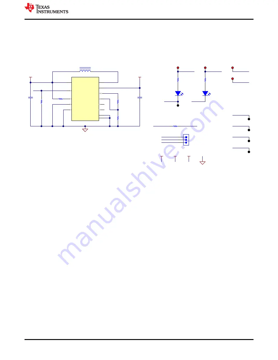
4 Schematics, PCB Layout, and Bill of Materials
The following sections contain images with the full schematics and layout prints, as well as a bill of materials
table, for the circuitry on the ADC-PHI-PRU-EVM.
4.1 Schematics
illustrate the schematics for the ADC-PHI-PRU-EVM.
GND
DGND
VIN_3V3
EVM_DVDD
TP5
TP1
TP2
VIN_3V3
VIN_5V0
Green
2
1
D1
1.50k
R5
Green
2
1
D2
DGND
DGND
TP3
EVM_DVDD
TP4
DCDC_5V5
TP6
DGND
TP7
DGND
TP8
DGND
TP9
DGND
VIN_5V0
VIN_3V3
VIN_1V8
VIN_5V0
VIN_3V3
VIN_1V8
1
2
3
J11
TSW-103-07-G-S
VIN_1V8
LVI1
1
LVI2
2
VIN
3
SW
4
ILIM
5
EN
6
FB
7
VOSNS
8
VOUT
9
GND
10
HVO2
11
HVO1
12
PAD
13
TPS61096ADSSR
U1
2.00k
R6
2.7 H
µ
L1
45.3k
R8
10.0k
R11
VIN_5V0
DCDC_5V5
GND
10.0k
R7
10V
4.7 F
µ
C4
10 F
µ
25V
C5
1.50k
R4
HSE_GPIO0_30
EVM_ID_PWR
VIN_3V3
0
R12
Figure 4-1. ADC-PHI-PRU-EVM Power Schematic Page
Schematics, PCB Layout, and Bill of Materials
SBAU396 – MAY 2022
ADC-PHI-PRU-EVM Evaluation Module
9
Copyright © 2022 Texas Instruments Incorporated


