TESTING
Bluhm & Feuerherdt GmbH
Production and Distribution of
Systems for the Testing of
Construction Materials
Motzener Str. 26b
DE - 12277 Berlin, Germany
Tel. +49 / 30 / 710 96 45-0
Fax +49 / 30 / 710 96 45-97
www.testing.de
1
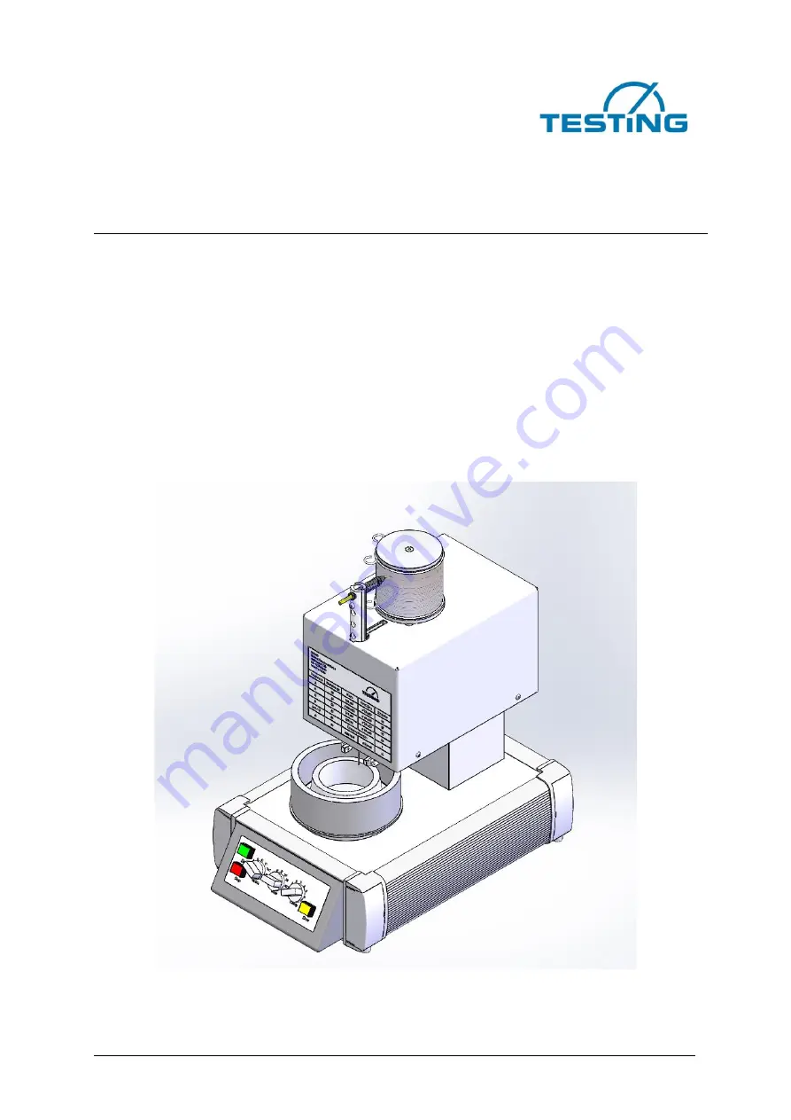
Operating Manual
Automatic Vicat Needle Apparatus


