


Description
Testboy
®
TV 470
47
ENGLISH
Connection socket
GND Ground
cable
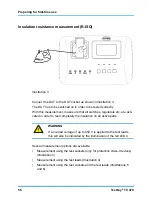
R Resistance
measurement
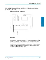
V+ Voltage
measurement
PELV
Protection low voltage measurement
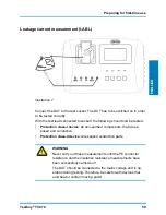
I current
measurement
Buttons
The operation of the button varies according to the menu position.
The current function of the underlying key is shown on the bottom line of the
display.
LED Indicators
LED 1 Green
OK / Value within the directive
LED 2 Yellow
Overrun (choose a larger range)
LED 3 Red
Value outside of the directive
LED 4 Red
Warning! Voltage on the connection socket V+
LED 1 and LED 3
Value can be OK but beware of the specifications.
The evaluation of the measurement data through LED1 and LED3
correspond only to the limits of the "normal" protection class-I de-
vices. The assessment is only considered to be as an aid. Refer to
the appendix of this manual or the relevant standard for the appli-
cable limits.
Summary of Contents for TV 470
Page 1: ...TV 470 Version 1 1...
Page 17: ...Inbetriebnahme Testboy TV 470 17 DEUTSCH Bild 1 Bild 2...
Page 20: ...Inbetriebnahme 20 Testboy TV 470 Bild 5 Bild 6...
Page 55: ...Preparing for first time use Testboy TV 470 55 ENGLISH Illustration 1 Illustration 2...
Page 58: ...Preparing for first time use 58 Testboy TV 470 Illustration 5 Illustration 6...
Page 93: ...Ingebruikneming Testboy TV 470 93 NEDERLANDS Afb 1 Afb 2...
Page 96: ...Ingebruikneming 96 Testboy TV 470 Afb 5 Afb 6...
Page 131: ...Prepara o para a primeira utiliza o Testboy TV 470 131 PORTUGU S Figura 1 Figura 2...
Page 134: ...Prepara o para a primeira utiliza o 134 Testboy TV 470 Figura 5 Figura 6...
Page 155: ......
Page 156: ......
Page 157: ......
Page 158: ......
Page 159: ......