TI3500 GPU-24
26
5
Unit Care and Maintenance
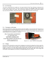
Testing the Universal Receptacle
2.
Place the positive probe on one of the four
screws securing the DC Output Connector
to the unit casing. Move the negative probe
to the dc negative post on the DC Output
Connector. Multimeter should read 0 Volts.
3.
Place the negative probe on one of the four
screws securing the DC Output Connector to
the unit casing. Move the positive probe to
the dc positive post. Multimeter should read
0 Volts.
3.
Move the positive probe to the dc
positive post on the DC Output
Connector. Multimeter should
read greater than 10 MΩ.
4.
Move the positive probe to the dc
negative post on the DC Output
Connector. Multimeter should read
greater than 10 MΩ.
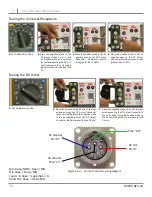
M to Case/GND = Open/ MΩ
K to Case = Open/ MΩ
J and L to Case = Less than 1 Ω
A and H to Case = Open/MΩ
Figure 5.5.3 – AC Input Connector wiring diagram
AC Hot
Pin “K”
AC Neutral
Pin “M”
AC Ground
Pins “J,L”
Pins “A,H”
1.
Set multimeter to Volts.
1.
Set multimeter to Ohms.
2.
Place the negative probe on the
AC ground probe ( J or L) and
the positive probe on one of the
four screws securing the DC Out-
put Connector to the unit casing.
Multimeter should read less than
1 Ω.
Testing the DC Outlet

