


59
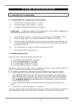
VII. NORMAL OPERATING INSTRUCTIONS
7.1.1 Starting UPS from a completely shut down position:
1.
Turn ON S1 (AC Input) switch (switch to ‘’1’’ position)
2.
Turn ON S2 (Bypass) switch (switch to ‘’1’’ position)
3.
Turn ON S4 (AC Output) switch (switch to ‘’1’’ position)
ATTENTION!!!
BYPASS VOLTAGE WILL BE CONNECTED TO THE OUTPUT TERMINALS OF
UPS WHEN THE ON/OFF SWITCH (S7) IS SWITCHED ON !
4.
Turn on S7 (On/Off) switch (to ‘’1’’ position). LCD panel activates, and ‘’INV RESET” or “PFC
RESET’’ message appears on the display meaning that the rectifier starts to operate.
5.
A few seconds later red bypass light (L2) on front panel turns off and gren inverter light (L6) turns
on. L6 light indicates that the UPS has started normal operation and generating uninterruptable
power for the critical load.
6.
Turn on S5 switch (to “1” position) to connect the battery group to UPS.
7.
UPS is ready and in normal operation now.
7.1.2 Shutting down the UPS
After closing all the critical loads supplied by the UPS output:
1.
Turn off S4 (AC Output) switch (to ‘’0’’ position).
2.
Turn off S7 (On/Off) switch (to ‘’0’’ position).
3.
Turn off S5 (Battery) switch (to ‘’0’’ position).
4.
Turn off S2 (Bypass) switch (to ‘’0’’ position).
5.
Turn off S1 (AC Input) switch (to ‘’0’’ position).
After performing the above procedure, UPS is completetely shut-down. In this case PFC rectifier and
inverter is not operating and the batteries are not being charged.
7.1.3 Switching the UPS from a Normal Operation to Maintenance Bypass Condition
1.
Enter COMMANDS menu by using UP and DOWN buttons on front panel during normal operation.
Select ENTER<BYPASS> command by using again the UP and DOWN buttons and pres ENTER
button. The critical load is transferred to bypass supply in this case and it is shown at LCD display
with
“A09 MANUAL BYPASS”
message. Besides L6 (load on UPS) light on front panel will be off
and L2 light (bypass) will be on.
2.
Turn on S3 (Maintenance Bypass) switch (after unlocking and taking away the padlock on it) to ‘’1’’
position.
3.
Turn off S7, S5, S1, S2 and S4 switches (to ‘’0’’ position).
In this case, bypass voltage is connected directly to the output of UPS and the critical load is supplied via
maintenance bypass switch. No AC or DC supply is connected to the inside and the circuits of UPS.
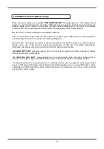
7.1 OPERATING UPS IN ONLINE MODE
Summary of Contents for DS300SHP Series
Page 1: ...DS300SHP SERIES DSP Controlled UPS 10 15 20 kVA 3 Phase IN 3 Phase OUT USER MANUAL...
Page 2: ......
Page 17: ...15 Figure 2 3 External Battery Connections 60x12V 30x12V Batteries 30x12V Batteries...
Page 18: ...16 Figure 2 3a DS300SHP Series 10 15 20 KVA Internal Battery Connections 60x12V 5Ah...
Page 19: ...17 Figure 2 3a DS300SHP Series 10 15 20 KVA Internal Battery Connections 60x12V 7 9Ah...
Page 70: ......
Page 71: ...AGKK12630 04 2017...


