background image

8


NOTE: In order to control the Gate/Vibratory Motor 

the Spinner/Auger must be active, if it is not active the 

Gate/Vibe label state will blink indicating the motor is 

disabled. 

Main Menu

Pressing the menu button will enter the main menu.

Once in the main menu, the user can select the following:

Operation

Default Motor Controls

Starting and  

Stopping Spreader

Press the ON button to turn on 

the spinner/auger.

Press the OFF button to turn off 

the spinner/auger

Gate/Vibe Control

Press the OPEN/ON button to 

open the gate or to turn on the 

vibe. 
Press the CLOSE/OFF button to 

close the gate or to turn off the 

vibe.

Adjusting Motor 

Speed

Press the bottom left button 

(down arrow) to decrease the 

speed of the motor in 11% 

increments.
Press the bottom mid button (up 

arrow) to increase the speed of 

the motor in 11% increments.

Entering the Menu

Press the bottom right button 

(menu) to enter the menu.

Maintenance Menu
Reverse Auger

The reverse auger feature allows users to reverse the 

auger in case of a jam.

To activate the reverse auger feature:

1.  Select maintenance for the main menu.
2.  Press start. The auger will pulse 3 times and the start 

button changes to pulsing to indicate the auger is 

turning.

3.  If the auger needs to be reversed further, press start 

again and wait for the reverse cycle to complete.

4.  Press the exit button to return to the main menu.
5.  If jam cannot be cleared, refer to cleaning auger 

section

Menu Options

Diagnostics

Review the warning and fault list.

Maintenance

Displays maintenance menu with 

options to reverse auger.

Settings

Adjusts the parameters of the display.

System

Display system’s voltage and 

temperature.

Support

Displays support information.

Controller Info Displays controller information
Display Info

Displays system information.

Exit

Returns to the home page.

Summary of Contents for 45-0592

Page 1: ...ons prior to using equipment BLACK PMS TBD CMYK C0 M0 Y0 K100 RGB R0 G0 B0 Hex 000000 Thread Black GREY PMS 428 CMYK C27 M17 Y17 K0 RGB R195 G197 B200 Hex c3c5c8 Thread Light Gray BLUE PMS 287 CMYK C1...

Page 2: ...an and dry Do not operate the engine in a confirmed space where dangerous carbon monoxide fumes can collect Never lubricate service or adjust the machine or attachment while it is moving Keep safety d...

Page 3: ...include pesticides herbicides and fungicides A Material Safety Data Sheet MSDS provides specific details on chemical products Physical and health hazards safety procedures and emergency response techn...

Page 4: ...otential safety hazards whenever necessary in special messages that are identified with the word CAUTION and the safety alert symbol Replace missing or damaged safety labels Use this operator s manual...

Page 5: ...ree point hitch If no front attachment is installed on vehicle ballast may be required to stabilize vehicle Refer to vehicle manual for proper ballasting A Qty Description 1 Spreader Qty Description 1...

Page 6: ...er Coil any extra harness and secure with wire ties Connect the circular connector on the display harness to the rear of the display Hand tighten until is fully seated DO NOT over tighten DO NOT cross...

Page 7: ...ory motor for improved material flow Variable Speed Auger Adjustable gate for precise material application From the operation page an operator can power on the spreader enter the menu or spinner speed...

Page 8: ...motor in 11 increments Entering the Menu Press the bottom right button menu to enter the menu Maintenance Menu Reverse Auger The reverse auger feature allows users to reverse the auger in case of a ja...

Page 9: ...Ensure that all harnesses are installed correctly and connectors are fully seated Ensure that the status light on the motor controller is green Spreading NOTE Always use the hopper cover to prevent m...

Page 10: ...clumps of material and help the material to flow into the rotor tray Attempt to spread again 3 If the rotor is stalled and jammed Disconnect the spreader harness from the control box Follow the steps...

Page 11: ...every 20 hours of use Apply lubrication prior to storage Cleaning To protect from corrosion clean spreader after every use with warm water and mild detergent Do not leave material in the spreader Mai...

Page 12: ...12 2 3 4 6 10 5 11 8 7 11 10 1 9 45 0593 Drop Spreader 2 In Receiver...

Page 13: ...ter Pin 1 7 ST50468 Clamp 1 2 ID x 75W Vinyl Coated 1 8 ST65136 Bolt 3 8 x 1 Carriage S S 12 9 ST65126 Nut 3 8 Flange S S 12 10 ST65122 Bolt 5 16 x 3 4 Carriage S S 14 11 ST65124 Nut 5 16 Flange S S 1...

Page 14: ...14 45 0592 Drop Spreader with 3 Pt Hitch Mount 3 7 8 4 5 10 2 1 6 11 12 9 13 14 15 17 16...

Page 15: ...oated 1 10 ST65135 3 8 x 1 1 4 Carriage Bolt S S 4 11 ST65136 3 8 x 1 Carriage Bolt S S 16 12 ST65126 Nut 3 8 Flange S S 20 13 ST65122 Bolt 5 16 x 3 4 Carriage S S 10 14 ST65124 Nut 5 16 Flange S S 10...

Page 16: ...16 ITEM NO PART NUMBER DESCRIPTION QTY 1 SA10018 Hopper Assembly 1 2 ST50478 Tray Assembly 1 3 ST50432 Lid Assembly 1 3 1 2 Drop Spreader Assemblies...

Page 17: ...17 This Page Intentionally Left Blank...

Page 18: ...18 SA10018 Drop Spreader Hopper Assembly 7 36 23 22 35 41 39 19 38 28 34 14 13 12 29 11 18 30 40 20 21 19 39 4 9 26 24 15 37 27 10 32 25 5 42 39 17 38 16 1 2 42 33 25 10 6 24 15 26 37 3 8 31 43 44 38...

Page 19: ...ng Pin 5 8 dia S S 2 25 ST50451 Rubber Latch 2 26 ST50423 Rubber Isolator 4 27 ST50424 Rubber Bumper 2 28 ST50468 Clamp 1 2 ID x 75W Vinyl Coated 3 29 ST65138 3 8 x 1 1 4 S S Hex Bolt 4 30 ST65127 Nut...

Page 20: ...20 9 6 27 24 20 14 17 19 22 8 7 18 6 27 24 3 29 26 4 2 1 27 11 25 16 15 5 10 12 21 23 24 28 13 ST50478 Drop Spreader Tray Assembly...

Page 21: ...16 x 1 1 4 1 14 ST50435 Sprocket 35 Series 9T 1 15 ST50472 Sprocket 48 Tooth 1 16 ST50470 Chain 35 Series 1 17 ST50452 Motor Electric 1 18 ST50468 Clamp 1 2 ID x 75W Vinyl Coated 1 19 ST65132 M6 x 12...

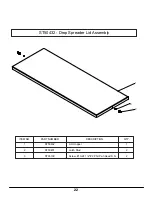
Page 22: ...22 ITEM NO PART NUMBER DESCRIPTION QTY 1 ST50432 Lid Hopper 1 2 ST50451 Latch Stud 2 3 ST65130 Screw 10 24 1 2 2 Phil Pan Head S S 2 2 3 1 ST50432 Drop Spreader Lid Assembly...

Page 23: ...23 This Page Intentionally Left Blank...

Page 24: ...24 SA10051 Controls and Wiring 1 2 3 7 6 8 4 5...

Page 25: ...Screw 4 6 ST48296 Mounting Socket 1 7 ST65148 10 24 Nylock Nut S S 2 8 ST65001 10 24 x 1 Truss Head Screw 2 2 285 Battery Harness Universal 1 2 286 Extension Harness Universal 1 2 459 Display Harness...

Page 26: ...26 This Page Intentionally Left Blank...

Page 27: ...27 This Page Intentionally Left Blank...

Page 28: ...s of merchantability fitness for any particular purpose and non infringement are hereby disclaimed and excluded Any product which does not meet warranty shall as purchaser s sole and exclusive remedy...

Reviews: