Terrain King KB21 Service Manual Download Page 88

KB21 Service Manual Pub 09-14

88

Mowers & Spindles

60-B.  Spindle 

Asy Repair


Spindle Housing Assembly

If installing new bearings, be sure to install new bearing cups (races). When installing the bearing cups,

make sure that they are properly seated into the housing. DO NOT DRIVE AGAINST THE BEARING

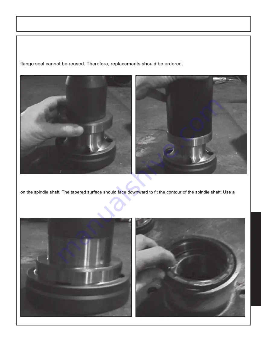
SURFACE. All parts should be thoroughly cleaned. The bearing nut, the lower seal and the motor 

Place a thin coat of silicone on the inside (tapered side) of the bearing ring (Fig-N). Place the bearing ring (Fig-O) 

piece of 2-3/4” 16 gauge tubing, 8” long to drive the bearing ring down on to the spindle until the bearing

ring bottoms out against the spindle (Fig-P). Remove any excess silicone from the spindle shaft and bearing ring.

Turn the housing upside down so that the bearing seal and retaining ring may be installed. Lubricate the

seal prior to installation (Fig-R).

FIGURE - O

FIGURE - P

FIGURE - Q

FIGURE - R

Summary of Contents for KB21

Page 1: ...KB21 10 14 2014 37002994247S ...

Page 2: ...KB21 Service Manual Pub 09 14 2 ...

Page 3: ...KB21 Service Manual Pub 09 14 3 1 800 882 5756 1 800 882 5758 ...

Page 4: ...ntenance and Service Safety Instructions and Practices 18 Transporting Safety Instructions and Practices 21 Concluding Safety Instructions and Practices 22 Decal Locations 23 Decal Descriptions 25 Federal Laws and Regulations 31 Tractor Side Definition 32 Mounting Work Site Requirements 33 Warning Do Not Weld 34 Section 30 Hydraulics 35 30 AHydraulic Control Circuits 37 Boom Control Circuits 39 30...

Page 5: ...ntrol Circuit 50 One Way Restrictors 52 Valve Sections Function 52 Hose End Fitting Torque Specification 52 Work Port Relief Operation 54 Anti Cavitation Check Work Port Relief Operation 55 Control Circuit Main Relief Valve Operation 56 Remote Cable Operation and Installation 57 Control Assembly Controller End Installation Procedure 59 Mechanical Control Valve 61 ValvePorts 62 40 B Bucher Series L...

Page 6: ...6 Typical Modes of Failure 77 Motor Mount Flange Spindle Housing Breaking or Cracking 81 60 B Spindle Assembly Repair 83 Spindle Housing 84 Spindle Housing Inspection 87 Spindle Housing Assembly 88 Section 80 Testing 93 80 A Mechanical Control Valve 94 Section 90 References 97 90 A Pump Repair 98 90 B Pump Repair Part Location 109 90 C Pump Shaft Issues 111 90 D Hydraulic System Operation 113 90 E...

Page 7: ...KB21 Service Manual Pub 09 14 7 Section 10 Safety ...

Page 8: ...KB21 Service Manual Pub 09 14 8 ...

Page 9: ...KB21 Service Manual Pub 09 14 9 ...

Page 10: ...KB21 Service Manual Pub 09 14 10 ...

Page 11: ...KB21 Service Manual Pub 09 14 11 ...

Page 12: ...KB21 Service Manual Pub 09 14 12 ...

Page 13: ...KB21 Service Manual Pub 09 14 13 ...

Page 14: ...KB21 Service Manual Pub 09 14 14 ...

Page 15: ...KB21 Service Manual Pub 09 14 15 ...

Page 16: ...KB21 Service Manual Pub 09 14 16 ...

Page 17: ...KB21 Service Manual Pub 09 14 17 ...

Page 18: ...KB21 Service Manual Pub 09 14 18 ...

Page 19: ...KB21 Service Manual Pub 09 14 19 ...

Page 20: ...KB21 Service Manual Pub 09 14 20 ...

Page 21: ...KB21 Service Manual Pub 09 14 21 ...

Page 22: ...KB21 Service Manual Pub 09 14 22 ...

Page 23: ...KB21 Service Manual Pub 09 14 23 ...

Page 24: ...KB21 Service Manual Pub 09 14 24 ...

Page 25: ...KB21 Service Manual Pub 09 14 25 P N 30002988455 ...

Page 26: ...KB21 Service Manual Pub 09 14 26 P N D624 ...

Page 27: ...KB21 Service Manual Pub 09 14 27 P N D688 P N D622 ...

Page 28: ...KB21 Service Manual Pub 09 14 28 P N D626 P N D619 P N D620 ...

Page 29: ...KB21 Service Manual Pub 09 14 29 P N D621 P N D835 ...

Page 30: ...KB21 Service Manual Pub 09 14 30 P N D637 P N D617 P N D623 ...

Page 31: ...KB21 Service Manual Pub 09 14 31 ...

Page 32: ...KB21 Service Manual Pub 09 14 32 ...

Page 33: ...KB21 Service Manual Pub 09 14 33 Safety ...

Page 34: ...KB21 Service Manual Pub 09 14 34 Safety ...

Page 35: ...KB21 Service Manual Pub 09 14 35 Section 30 Hydraulics SubSections 30 A Hydraulic Control Circuits 30 B Hydraulic Tanks 30 C Hydraulic Pumps ...

Page 36: ...KB21 Service Manual Pub 09 14 36 ...

Page 37: ...e array of actuators and motors with very high power density The use of hydraulics involves a hydraulic transmission which can be related to mechanical transmis sions designs and gear ratios In the diagram if the small cylinder is 1 inch in radius and the large is 10 inch in radius and the force exerted on the small cylinder is 10lbs the resulting force on the big cylinder would be 100 times the s...

Page 38: ...ugh in order to provide the work required Terrain King utilizes two separate hydraulic circuits to control the work required on the Terrain King boom mowers 1 Boom control system which provides the control and movement of the boom functions such as the swing lift dipper head tilt door and head twist functions controlled by a joystick or through cable operation 2 Motor control system provides the c...

Page 39: ...lve spools are in neutral provides a passage directly to tank These valves are most commonly used valve at all times when the pump is turning or when the tractor engine is running the valve until one of the spools in the valve is moved to allow some of the oil to be diverted to a cylinder to perform work The performance or speed of a valve is a function of four characteristics of the load 1 Weight...

Page 40: ...wers with open center valves are designed to provide superior performance when more than one function is operated simultaneously The perception of poor performance may be representative of poor operating procedures In addition many operators have a tendency to operate the tractor with the throttle wide open or in the All Terrain King boom mowers should be operated at the pto shaft 540rpm setting n...

Page 41: ... Make certain no hydraulic cylinders are supporting any weight work the control valves to release any pressure Make certain tractor has been shut down and sat long enough that all pressure is relieved cover clockwise to lift it up and off Lift it up slowly as there is a spring under this cover tion the housing may still have oil in it ...

Page 42: ...ounter clockwise until the three bolts slide into the slots Replace the bolt that was removed previously Tighten the four bolts in increments until the cover is seated evenly all the way around Do not force cover down with bolts if it offers resis tance Tighten the bolts in an even manner ...

Page 43: ...e Use of a rear mounted PTO driven pump requires the pump to be set up to operate in the reverse rotation hose to port M2 on the motor control valve The oil exits the valve through port T through return line to See the motor control valve section for detailed explanation of the valve operation A non adjustable pressure relief valve located on the motor control valve block and set at 3000 PSI prote...

Page 44: ...on of the cutter motor circuit The cutting circuit section is the section and is located infront of the cutting circuit section when mounted Viewing the cross section of one of the gear Sections in Pump can illustrate the Flow of the Oil through the section along with the physical results KB21 control ...

Page 45: ...and squeezes them against the gear faces This provides a seal between the gear face and the thrust plate surface preventing the high pressure oil from leaking back to the low pressure inlet side Mechanical seals on the thrust plate prevent oil from leaking between the plate and the adjoining casting The seals de picted in the illustration are known as Pocket seals a channel type seal may be used o...

Page 46: ... operator s position In most cases the control valve is located below the swing cylinder mount and attached to the main frame of the boom The Motor Control Valve used on the Terrain King Boom Mower utilizes 2 Pilot controlled logic valves to tank In addition the Motor control valve uses a 1850 relief pressure brake system to stop the rotating blades after the operator shuts off the mower Terrain K...

Page 47: ...KB21 Service Manual Pub 09 14 47 s Section 30 30 C Motor Control Valve Function Motor Control valves utilize logic valves to provide the mower power and mower brake functions ...

Page 48: ...KB21 Service Manual Pub 09 14 48 Section 40 Cylinder Control Systems 40 A Bucher L 8S Manual Control Cable 40 B Bucher L 8S Electronic Joystick Control ...

Page 49: ...ce Manual Pub 09 14 49 Cylinder Control Systems 40 A Bucher L 8S Manual Control Cable Bucher Series L 8S Open Center Directional Control Valve Manual Control L 8S 4 Spool control valve L 8S 4 Spool control valve ...

Page 50: ...ure relief valve is factory set at 2000 PSI on the KB21 Boom In addition some individual cylinder circuits are protected by a nonadjustable work port relief valve See Specifications The port relief valves set specific pressures for the boom function to provide over pressure protection Oil is returned from the valve through the motor control valve to the tank where it passes through the The valve u...

Page 51: ...KB21 Service Manual Pub 09 14 51 Cylinder Control Systems 40 A Bucher L 8S Manual Control Cable ...

Page 52: ...n Hose End Type 37 Degree Angle End Steel Hose End Fittings Dash Size Nominal Cyl Size in Torque in lbs Torque 4 1 4 140 12 6 3 8 230 19 8 1 2 450 38 10 5 8 650 54 12 3 4 900 75 16 1 1200 100 20 1 1 4 1600 133 24 1 1 2 2000 167 32 2 2800 233 Note Straight threads do not always seal better when higher torgue are used Too much torque causes ...

Page 53: ...ool is in the neutral position shown above oil from the pump is available at the parallel The oil travels through all of the valve sections by way of the parallel passage until it reaches the end cap where it is directed to the tank passages which travel through the valve sections and back to the oil supply tank The oil in the system is under very low pressure due to the lack of load or restrictio...

Page 54: ...tection of the circuit from over pressure due to inadvertent loading of the cylinder such as from impact with a solid object As indicated the pressurized oil is also present at the work port relief when the spool is shifted from the neutral position to operate the cylinder In this instance the oil will be relieved at the work port relief set pressure rather than the higher main relief pressure The...

Page 55: ...e up oil from the return tank port to the cylinder during gravity assisted operation of the cylinder This prevents the possibility of the entry of air into the circuit due to the negative pressure created while the cylinder is operating The negative pressure created by the movement of the cylinder overcomes the anti cavitation spring pressure and allows the oil at the tank port to travel through t...

Page 56: ...re circuit rather than an individual section from the possibility of damage due to over pressurization Pressure in excess of the set pressure of the main relief spring will overcome the spring tension and unseat the piston This allows the pressurized oil to travel directly to tank Once pressure is reduced tank pressure setting All control valve main relief s for the KB21 mowers are factory pre set...

Page 57: ...ractors as well Four cable lengths are available and should be ordered based on the length required to reach from the valve to the Operator s location with out binding or kinking Cable lengths are limited to 48 60 72 and 102 inches To install the cables to the valve refer to the controller installation instructions in this manual Turn the cable eye Jam nut on the threaded cable end until it bottom...

Page 58: ...the threaded turning on the assembly make sure that the valve spool remains in the neutral position Tighten the Jam Nut onto the Flange Sleeve Assembly to lock it into position Tighten the Flange into position using the two Allen washer on each bolt Interference will occur between the Flange Sleeve Assembly and the casting of the Inlet Section on the Valve Section next to the Inlet Section To comp...

Page 59: ...attachment nut and tighten Allow the controller handle to return to neutral Slide the cable guide tube into the control housing and reinstall and tighten the housing screw Check the operation of the spool cable and controller Some adjustment at the valve end may be required too ensure that the spool returns to neutral when the controller is in the neutral position The control lever assemblies util...

Page 60: ...KB21 Service Manual Pub 09 14 60 Cylinder Control Systems 40 A Bucher L 8S Manual Control Cable ...

Page 61: ...se one component can be the cause of another component failure Information collection any information on unit from operator will be helpful 1 What is model unit size type head type tractor it is mounted on etc 2 What is not working correctly In as much detail as possible 3 Has this malfunction existed for some time just start suddenly continuous malfunction or off and on when does malfunctions occ...

Page 62: ...ylinder Valve Ports designated as A Ports connect to the Barrel End of Swing and Lift Cylinder and to the Rod End of the Dipper and Tilt Cylinder One Way Restrictors alve from the Cylinder The illustration depicts a standard 4 Spool Valve Valve Sections Function Dash Size Nominal Cyl Size in Torque in lbs Torque 4 1 4 140 12 6 3 8 230 19 8 1 2 450 38 10 5 8 650 54 12 3 4 900 75 16 1 1200 100 20 1 ...

Page 63: ...KB21 Service Manual Pub 09 14 63 Cylinder Control Systems 40 B Bucher L 8S Electric Control Cable Bucher Series L 8S Open Center Directional Control Valve Electrical Control ...

Page 64: ...KB21 Service Manual Pub 09 14 64 Cylinder Control Systems 40 B Bucher L 8S Electric Control Cable ...

Page 65: ... the circuits is obtained from a switched and fused tractor voltage source This means that the electrical power wire to the joystick controller should only be connected to a wire that has voltage when the ignition is in the ON position If connection of the joystick controller is to a constant current source it will cause power drain on battery and eventually battery failure Furthermore the master ...

Page 66: ...ents must work 1 The joystick controller is moved in the correct direction and during its movement an electrical signal is sent to the electric controller in the proper valve section of the control valve 2 The electric signal causes the controller to actuate 3 Reaction time from the time the joystick is moved until the spool moves is approximately 300 milliseconds ...

Page 67: ... at the valve end are changed then the Plug would still be connected the same way and be Wrong If any connections are removed they MUST be placed back in the same order they came out of See Wiring schematic on the following pages S for Plug Connection Letter Code Terminal locations See Figure Schematic for actual Wire locations DO NOT CHANGE LOCATIONS OF PINS AND OR WIRES IN PLUGS THEY MUST BE CON...

Page 68: ...KB21 Service Manual Pub 09 14 68 Cylinder Control Systems 40 B Bucher L 8S Electric Control Cable ...

Page 69: ... stop the blades from rotating in 6 second from time switch is activated The E Stop switch will not allow the head to start when activated the switch is engaged if you are unable to get Some parts may not be available as replacement parts for this switch available as an assembly only The emergency stop switch is mounted in the arm rest if it is not mounted in arm rest it must be mounted where oper...

Page 70: ...ntrol valve is an Electro hydraulic Electric over Fixed Displacement Gear Pump to facilitate movement of the boom Components The use of a Fixed Displacement Pump means that when the tractor is running the pump is pumping shut off Likewise the Oil Flow from the pump through the valve is controlled by the RPMs of the tractor engine the boom funtions ...

Page 71: ...the neutral determines the pump pressure Pump pressure at the neutral position will be equal to standby pressure When one or more of the main spools are activated the load pressure is fed through the shuttle or load sense valve circuit to the spring chamber behind the pressure bypass adjustment spool This needed The pilot reducing valve maintains standby pilot oil pressure to the proportional cont...

Page 72: ... in the swing lift and dipper circuits to limit the max pressure in those particular circuits to a lower pressure than the main system relief The anti cavitation check valve allows oil to be taken from the return tank t port galley of the valve when needed to prevent cavitation of cylinder The tilt and door valve sections do not contain these valves of oil to the cylinders The spool is actuated by...

Page 73: ...KB21 Service Manual Pub 09 14 73 Cylinder Control Systems 40 B Bucher L 8S Electric Control Cable ...

Page 74: ...listed are a guide to show approx what Cycle times for tour Unit should be Valve Leakage Maximum internal Valve Leakage from the Cylinder Ports to Tank at any Valve Segment Oil Pressure at 1450 PSI and Oil Viscosity at 102 SSU 1 25 Cubic Inch Minute Standby Pilot Pressure Standby Pilot Pressure 200 to 250 PSI Dash Size Nominal Cyl Size in Torque in lbs Torque ft lbs 4 1 4 140 12 6 3 8 230 19 8 1 2...

Page 75: ...KB21 Service Manual Pub 09 14 75 Section 60 Motors Spindles SubSections 60 A Rotary Mower 60 B Spindle Assembly ...

Page 76: ...KB21 Service Manual Pub 09 14 76 Mowers Spindles 60 A Rotary Mowers ...

Page 77: ...s Failed bolts should be returned for inspection Blade Bar Bent Due to abusive operation such as powering down close cutting or impacts Due to use of poor quality after market components Mower Head Structural Cracks Could be due to impact damage vibration abusive operation or manufacturing issues Contact customer service prior to adding additional weight to the mower head with bracing or gussets V...

Page 78: ...KB21 Service Manual Pub 09 14 78 Mowers Spindles 60 A Rotary Mowers insufficient l o g l l ...

Page 79: ...KB21 Service Manual Pub 09 14 79 Mowers Spindles 60 A Rotary Mowers ...

Page 80: ...KB21 Service Manual Pub 09 14 80 c d o s l l s c p v c B l O s s l h o h o F o g b p c m b l Mowers Spindles 60 A Rotary Mowers v v s ...

Page 81: ...unction relieving too soon Restrictions in the system Excessive hose bend or crimping Internal hose failure Incorrect hose sizing or material Contamination Faulty motor Motor Mount Flange Spindle Housing Breaking or Cracking This is normally due to improper torque or loss of torque of the motor mount bolts See proper installation instructions in the Product Service and Operator s manuals to obtain...

Page 82: ...stem Excessive hose bend or crimping Internal hose failure Incorrect hose sizing or material Contamination Excessive internal leakage due to wear contamination Relief valve malfunction relieving too soon Motor shaft external Leakage into the spindle Shaft seal worn due to debris or overpressure from spindle vent plugged Shaft seal falling out of bore due to retainer failure Shaft seal bore incorre...

Page 83: ...KB21 Service Manual Pub 09 14 83 Mowers Spindles 60 B Spindle Asy Repair ...

Page 84: ...hiseling or hammering on metal components Hardened metal will chip unexpectedly An assembled spindle housing is quite heavy Use a hoist or lift to handle them safely Always use proper lifting techniques when lifting heavy objects Spindle Housing Dis Assembly Drain the oil from the spindle assembly See Fig A Inspect the housing for cracks or other damage which would deem it unusable Place a 3 16 an...

Page 85: ...e bearing ring Rotate each bolt in a clockwise pattern 1 4 turn at a time for 2 1 2 revolutions Fig D Remove the original bolts and replace them with 4 shanked bolts In a clockwise pattern rotate each bolt 1 4 turn at a time until the spindle shaft is free from the housing Fig E F In some cases it may be necessary to use a drift punch and hammer to fully dislodge the shaft Care should be taken to ...

Page 86: ... screwdriver to remove the seal retaining ring Fig H Pry out the lower seal BE CAREFUL NOT TO DAMAGE THE SPINDLE HOUSING A new seal is required for rebuild of the spindle Fig I Remove the bearing and check it for damage or excessive wear Fig J FIGURE G FIGURE H FIGURE I FIGURE J ...

Page 87: ...ection Inspect the bearings and bearing cups for nicks pitting discoloration and wear If any exist replace the bearing and bearing cup Inspect the housing for cracks wear at the bearing cup bores or impact damage Replace if necessary Inspect the spindle shaft for pulled bolt threads cracks adjusting nut thread damage or machined surface damage Replace if required FIGURE K FIGURE L FIGURE M FIGURE ...

Page 88: ... bearing nut the lower seal and the motor Place a thin coat of silicone on the inside tapered side of the bearing ring Fig N Place the bearing ring Fig O piece of 2 3 4 16 gauge tubing 8 long to drive the bearing ring down on to the spindle until the bearing ring bottoms out against the spindle Fig P Remove any excess silicone from the spindle shaft and bearing ring Turn the housing upside down so...

Page 89: ...ng groove FIG T Be spindle sure the retaining ring is in the groove all the way around and the seal is against the retaining ring Place the spindle shaft with the bearing ring installed into the spindle housing Turn the assembly over so that the housing is sitting upright and the spindle shaft is supporting the housing FIG U Use the 2 3 4 tube to drive the lower bearing down onto the bearing ring ...

Page 90: ...l fill hole when it is in this position Install the upper bearing and race along with the bearing nut FIG X Tighten the new lock nut with a 4 prong socket and hand ratchet until tight Back the nut off until 12 to 15 INCH POUNDS of rolling resistence is achieved Use a punch to stake the bearing nut in place Be sure to stake the nut at both slot locations FIG Y Install the new motor flange gasket Ap...

Page 91: ...KB21 Service Manual Pub 09 14 91 Mowers Spindles 60 B Spindle Asy Repair ...

Page 92: ...KB21 Service Manual Pub 09 14 92 10 Mowers Spindles 2 3 4 1 5 6 8 9 7 10 9 8 60 B Spindle Asy Repair ...

Page 93: ...KB21 Service Manual Pub 09 14 93 Section 80 Testing Subsections 80 A Mechanical Control Valve ...

Page 94: ... movement of the cable controls throughout its complete range of movement Check the cylinder speeds look for jerky operation the cylinder should respond smoothly to the movement of the control valve controls Look for time delay between movement of controls and movement of cylinders 6 After checking each function attempt to duplicate the malfunction described by operator using the information gathe...

Page 95: ...ictions At 1800 rpm you should have 8 gpm and still 100 psi through tion pump section pressure gauge as you go increasing pressure in 500 psi increments There will be no need to ex ceed 2000 psi when doing this test Gpm will drop when under pressure but should not drop below 6 8 section on tandem pump option 6 If only one function of valve is not working it is easiest to visually check the relief ...

Page 96: ...KB21 Service Manual Pub 09 14 96 ...

Page 97: ...ice Manual Pub 09 14 97 Section 90 References Subsections 90 A Pump Repair 90 B Pump Repair Parts Location 90 C Pump Shaft Issues 90 D Hydraulic System Operation 90 E PVG32 Troubleshooting 90 F Safety References ...

Page 98: ... side would be the opposite of shown and the pump would be re assembled to where the marks would be on the other side References IMPORTANT Service Technician must add marks and or numbers to pump in 5 places to help in re assembly of pump 90 A REPAIR ...

Page 99: ...be assembled right away they should be coated with light coat of hydraulic oil and stored where they can not collect dust 5 Caution during disassembly use extreme caution when prying apart castings The marring of machined surfaces could cause leakage Excessive use of force can result in mis alignment and serious damage to parts Gears are closely matched and must be kept together as a set when remo...

Page 100: ...KB21 Service Manual Pub 09 14 100 C first h replace the Channel Seals References 90 A REPAIR ...

Page 101: ...KB21 Service Manual Pub 09 14 101 second If G C the s o h g h n It third g g h y References 90 A REPAIR ...

Page 102: ...KB21 Service Manual Pub 09 14 102 is to the s s h g fourth g g b g h References 90 A REPAIR ...

Page 103: ...KB21 Service Manual Pub 09 14 103 r p p o u c References 90 A REPAIR ...

Page 104: ...KB21 Service Manual Pub 09 14 104 1 2 3 h o L m o i g s s r g g s y m first f f s c s g b g h P c s d P c s p m f P s n o p g h o i s s o p t i s c s d References 90 A REPAIR ...

Page 105: ...KB21 Service Manual Pub 09 14 105 4 5 6 7 References 90 A REPAIR ...

Page 106: ...KB21 Service Manual Pub 09 14 106 8 9 10 11 12 References 90 A REPAIR ...

Page 107: ...KB21 Service Manual Pub 09 14 107 13 References 90 A REPAIR ...

Page 108: ...KB21 Service Manual Pub 09 14 108 14 15 16 17 References 90 A REPAIR ...

Page 109: ...KB21 Service Manual Pub 09 14 109 References 90 B PUMP REPAIR PARTS LOCATION ...

Page 110: ...ON 3 19 1 24 CU MOUNTING FLANGE HOUSING CONNECTION DUAL PUMP COVER FLANGE DUAL SUC PUMP HOUSING GEAR FRT PUMP ASY GEAR HOUSING DUAL SUC PUMP SET GEAR SHAFT FRT PUMP ASY SET GEAR DUAL SUC PUMP SHAFT CONNECT DUAL SUC PUMP SCREW CAP DUAL SUC PUMP STUD FRT PUMP ASY 3 91 1 24CU SCREW DRIVE FRT PUMP ASY NUT 5 8 NC PLB DOWEL PIN PUMP HYDRO 15 10 DOWEL PIN DUAL PUMP REAR THRPL FRT PUMP ASY THRPL DUAL PUMP...

Page 111: ...ump shaft and the splines of the crank shaft adapter without the shaft in the system Likewise vibration can be observed by watching for high frequency movement of the shaft during operation Rotating Bending Fatigue as evidenced by beach marks around the circumference Final fracture is Brittle rough center region FIG X Failure due to cyclical loads from misalignment 2 Sporadic overpowering of the d...

Page 112: ...KB21 Service Manual Pub 09 14 112 References 90 C PUMP SHAFT ISSUES ...

Page 113: ... environment CAVITATION is the development and explosion of air bubbles in the hydraulic system at the pump or of performance This type of damage is usually the result of the loss of oil in the tank or air leaks in the suction line to the pump It is also possible to cavitate the motor during shut down by completely stopping the tractor motor and front pump while the motor is still turning due to t...

Page 114: ...KB21 Service Manual Pub 09 14 114 References 90 D HYDRAULIC SYSTEM OPERATION ...

Page 115: ...KB21 Service Manual Pub 09 14 115 Reference 90 E PVG32 TROUBLESH OOTING ...

Page 116: ...KB21 Service Manual Pub 09 14 116 Reference 90 E PVG32 TROUBLESH OOTING ...

Page 117: ...KB21 Service Manual Pub 09 14 117 References 90 F Safety Refere nces ...

Page 118: ...KB21 Service Manual Pub 09 14 118 References 90 F Safety Refere nces ...

Page 119: ...KB21 Service Manual Pub 09 14 119 References 90 F Safety Refere nces ...

Page 120: ...KB21 Service Manual Pub 09 14 120 References 90 F Safety Refere nces ...

Page 121: ...KB21 Service Manual Pub 09 14 121 5HIHUHQFHV 6 DIHW 5 HIHUHQF HV ...

Page 122: ...KB21 Service Manual Pub 09 14 122 5HIHUHQFHV 6 DIHW 5 HIHUHQF HV ...

Page 123: ...KB21 Service Manual Pub 09 14 123 5HIHUHQFHV 6 DIHW 5 HIHUHQF HV ...

Page 124: ...KB21 Service Manual Pub 09 14 124 5HIHUHQFHV 6 DIHW 5 HIHUHQF HV ...

Page 125: ...KB21 Service Manual Pub 09 14 125 5HIHUHQFHV 6 DIHW 5 HIHUHQF HV ...

Page 126: ...KB21 Service Manual Pub 09 14 126 37002994247S ...

Reviews: