background image

14

 5.11

  System menu 

This menu tab contains following submenu items: “Event logs”, “Export parameters”, “Import parameters”, “Firmware 

upgrade”, “User management”, “Restore defaults“, “Restart the device“, “Auto Restart“, “Time, Date”, “Language”. Mouse 

over to show the list of this submenu.


5.11.1

  Event logs 

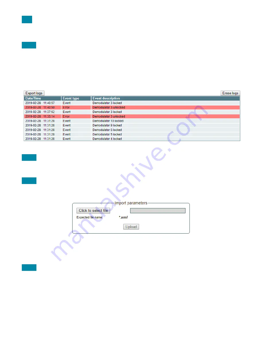
Various important events, errors, warnings will be logged into the system, see Figure 21 "Event logs". Each record has 

an event type, which can be used to filter particular messages. Just select checkboxes in the „Logs filtering“ table and press 

„Apply“. Other messages will be hidden.

„Erase logs“ button will erase all logs from the system. 

“Export logs” button forms the file (log.html) which will be downloaded to PC.

Each record has a log time when the event appeared. Refer to 

5.11.9 "Date, Time" 

settings for instructions how to 

configure time settings.


Figure 21. Event logs


5.11.2

  Export parameters

All settings of transmodulator can be exported for backup or copying to another device. Press “Export parameters” and 

“parameters.xml” file will be downloaded to PC. This file can be imported only to the same type of device.


5.11.3

  Import parameters

Exported parameters can be imported back to the device. Press onto “Click to select file” button (see Figure 22 "Import 

parameters") to select exported file.

Figure 22. Import parameters

Press “Upload” button to send the file to the device.It will take several seconds to update all parameters after file upload. 

After that, device will function with new configuration. No restart is required.


5.11.4

  Firmware upgrade  

Device firmware can be upgraded via web browser. Press the “Click to select file” button and select firmware binary file. If 

valid file was selected, a version number of new firmware will be displayed. Otherwise an error message will appear. Press 

the “Upload” button to upload new firmware to the device. Upload progress bar will appear and may take several seconds 

to upload, depending on the size of a file and a network connection speed. A message will be displayed asking to restart 

the device when the file was sent to the device. New firmware will be programmed into the device only after restart. It may 

take additional minute or more to flash new program. Device will start up with a new firmware and continue to operate with 

previous parameters. Additional new firmware features (if any) may need to setup additionally to take effect.

Avoid power supply interruption when a programming process is going on.

Device has possibility to load software revision history and check availability for new software release. Click the “Check 

online” link. If computer (not device!) has internet access, it will show a list of all software releases with links to binary files. 

Binary file can be downloaded and saved to computer (see Figure 23 "Firmware upgrade"). After that, use the firmware 

upgrade method as described above.

Summary of Contents for S3C32VB

Page 1: ...Vers 1 02 32 channels DVB S S2 to 16 32 DVB C transmodulators S3C32VB S3C32WB User s manual EN ...

Page 2: ...connect plugs from mains socket The mains sockets must be easily accessible The headend shall not be exposed to dripping or splashing water and no objects filled with liquids such as vases shall be placed on it Avoid placing device next to the central heating components and in areas of high humidity No naked flame sources such as lighted candles should be placed on headend If the device has been k...

Page 3: ...N 2 DC OUT 2 EN50607 1Amax 0 13 18 V RF TEST 20 dB RF OUT 8 10 11 14 15 12 13 Bottom view Front view S3C32WB 32 mux DVB S S2 32 DVB C Transmodulator POWER SUPPLY 1 STATUS DC OUT 2 STATUS DC OUT 1 POWER SUPPLY 2 HEADEND ADDR STATUS 17 18 19 20 21 22 23 24 25 26 27 28 29 30 31 1 2 3 4 5 6 7 8 9 10 11 12 13 14 15 16 32 RESET 8 3 4 7 1 2 5 6 17 12 13 14 15 16 ...

Page 4: ...addressing indicator It blinks on when the device is being accesed via Web interface 2 HEADEND STATUS error indicator Red light indicates that at least one error exists at the moment 3 STATUS DC OUT 1 indicates LNB1 powering status 4 STATUS DC OUT 2 indicates LNB2 powering status 5 STATUS POWER SUPPLY 1 indicates correct DC voltage from power supply PS1 6 STATUS POWER SUPPLY 2 indicates correct DC...

Page 5: ...n Enter the user name and password and click on Login button NOTE the default password admin can and must be changed as explained in the section 5 11 5 User management During initial configuration you need to change the default control interface TCP IP configuration as explained in the section 5 9 IP settings NOTE If you are using Internet Explorer Web browser supported versions are version 10 or ...

Page 6: ...be displayed Make sure that Ethernet router is configured properly to pass SSDP packets 239 255 255 250 1900 and 239 255 255 246 7900 Also make sure that all devices are connected to the same Ethernet network Diagnostic information table It displays all device errors and comments how to eliminate them Figure 4 Diagnostic information table with errors 5 3 RF inputs Figure 5 Input 1 Input 2 table DV...

Page 7: ...11 725 MHz DiSEqC then DISEQC commands are used to select the satellite Possible commands Satellite A Satellite B Satellite C Satellite D Vertical or Horizontal polarization dSCR first select source type as shown in Figure 6 then select dSCR SCR mode Device must have direct connection to Unicable multiswitch or LNB Next select SAT input and User band type in frequencies symbol rate press Update bu...

Page 8: ... only if the device has synchronized with the input signal Modulation standard detected standard of the input signal Possible values of the standard DVB S DVB S2 Frequency intermediate frequency for DVB S S2 at the device input Modulation modulation scheme of the input signal Possible values of the modulation scheme QPSK 8PSK for DVB S S2 FEC forward error correction SNR RF signal noise ratio at t...

Page 9: ...numbers are added but TV does not recognize it check the following If TV supports LCN If Network ID and Original Network ID values are valid for the country which is selected on TV Enable dropbox enables the service to the selected output Descramble checkbox enables or disables descrambling Press onto sign and service information will be extended see Figure 12 Service details Figure 12 Service det...

Page 10: ...e 3 0x1D H 264 AVC frame compatible plano stereoscopic HD NVOD time shifted service see note 3 0x1E H 264 AVC frame compatible plano stereoscopic HD NVOD reference service see note 3 0x1F HEVC digital television service see note 4 0x20 to 0x7F reserved for future use 0x80 to 0xFE user defined 0xFF reserved for future use NOTE 1 MPEG 2 SD material should use this type NOTE 2 MPEG 1 Layer 2 audio ma...

Page 11: ...The 2nd table in the page describes Transport stream ID and Original network ID of each channel see Figure 15 Each stream in a network must have unique ID called Transport stream ID An Original_Network_ID is defined as the unique identifier of a network It can be linked to Network ID or used value from this location http www dvbservices com identifiers original_network_id page 1 Figure 15 Transpor...

Page 12: ...ises You can easily filter out needed output channels by selecting needed output in table TS Info This lets you quickly view and setup LCN for every channel also check your Output bitrate and ensure that it is not overflowing Figure 17 TS Info table ...

Page 13: ...l precise attenuator up to 2 5 dB in step of 0 5 dB Press Update to change settings In case if any modulation parameter was changed all channels will be restarted with new settings Exception is Attenuator changes in this parameter will not restart the modulator Figure 18 DVB C output parameters 16 32 independent QAM modulators can be setup in this section There is no requirement for channels to be...

Page 14: ...stem see Figure 19 IP settings table IP parameters will be updated immediately after pressing Update button and redirect to new location NOTE Press the RESET and default IP button for more than three seconds to set default IP address of the control Ethernet interface see Figure 1 External view of the device Figure 19 IP settings table 5 10 E mail settings The device can send e mail reports if erro...

Page 15: ...on to send the file to the device It will take several seconds to update all parameters after file upload After that device will function with new configuration No restart is required 5 11 4 Firmware upgrade Device firmware can be upgraded via web browser Press the Click to select file button and select firmware binary file If valid file was selected a version number of new firmware will be displa...

Page 16: ...d or user access account for another person you take full responsibility for all device settings modifications made by that person or anyone else they may give the password to 5 11 6 Restore defaults All parameters will be restored back to factory defaults after confirmation The exception IP address and users these parameters will be unchanged To restore IP address and system password to system de...

Page 17: ...5 11 10 Language Device control panel supports several preinstalled languages A change of language requires system restart Note that all previously logged records will remain in previous language Additional languages can be installed under request Contact our distributors for such possibility 6 Regions Device supports several preinstalled regions Region can be changed without restarting the device...

Page 18: ... MHz by 100 kHz step channel allocation independent output level per carrier impedance max 90 dBµV 75 Ω total output level adjustment 15 dB by 1 dB step carrier output level adjustment 2 5 dB by 0 5 dB step MER 43 dB modulation DVB C QAM16 QAM32 QAM64 QAM128 QAM256 channel bandwidth symbol rate 4 8 3 MHz 3 5 7 2 MS s roll off 15 signal processing EN 300 429 ITU T J 83 A Annex A test point 20 dB TS...

Page 19: ...TERRA UAB Draugystes str 22 LT 51256 Kaunas Lithuania Tel 370 37 31 34 44 fax 370 37 31 35 55 E mail sales terraelectronics com www terraelectronics com ...

Reviews: