background image

10

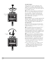
Verify Azimuth alignment 

Switch to Sat B (119°) on your on-screen menu, using
Transponders 23, 25, 29 or 31. Verify that signal is also
peaked at 119° by very slightly rotating the antenna around
the penciled marking on the mast. Once satisfied, tighten the
two Azimuth/Mast clamp bolts.

NOTE: 

Sat B (119°) signal strength may read different than

Sat A (101°) signal strength, depending on the satellite
transmission patterns in the area. You only need to see
whether Sat B (119°) is peaked and not try to compare
signal strength numbers. It’s OK to be close but not at the
peaks for both locations simultaneously.

Fine-tune the Elevation 

Use Sat B (119°) or Sat A (101°) on-screen signal meter. While
holding the LNB Arm, slightly loosen the two Elevation nuts.
Move it up/down slightly and observe the signal strength on the
screen. Find the peak and tighten the two Elevation nuts.

Verify satellite signals 

Confirm the final signal-peak readings at all three satellite
locations. Sat C (110°, Transponders 8, 10 and 12.) should 
be aligned automatically.

NOTE 1:

Occasionally, you may see a transponder at Sat A

(101°), Sat B (119°) or Sat C (110°) not active, it is
possible that this transponder is reserved for upcoming
programming expansion. Switch to other transponders at the
same satellite location to verify that you have good readings
and that your antenna alignment is satisfactory.

NOTE 2:

In most of the U.S., the Tilt Adjustment should be

fixed. However, because of large Tilt angle to 119° satellite in
Eastern Seaboard states, a small amount of Tilt fine-tuning
adjustment may improve 119° signal strength without
significantly changing 101° signal reading. For  these states,
the following Tilt fine-tuning procedures are recommended:

1.

Follow alignment procedures from Step 1 through Step 9;
tighten Elevation and Mast clamp bolts.

2.

Fine-tune Tilt Adjustment first by +3 degrees and then 
–3 degrees. Tilt is optimized when you see the 101°
signal reading essentially unchanged and 119° signal
strength improved by several points. Set Tilt to the
optimized point and tighten Tilt nuts.

Antenna

Transponder: 1, Sat A
Antenna Location:

Azimuth: 152 
Elevation: 50
Tilt: 102

Clear

OK

             Current Level: 0      Peak Level: 91 

Signal:

Antenna

Transponder: 23, Sat B
Antenna Location:

Azimuth: 152 
Elevation: 50
Tilt: 102

Clear

OK

             Current Level: 0      Peak Level: 75

Signal:

Verify Azimuth

Alignment

Fine-tune the

Elevation

Summary of Contents for Multi-Satellite Dish Antenna 1DIRECTV

Page 1: ...best results we suggest you read carefully through these pages first before beginning installation The guide is intended for an individual experienced in performing the various tasks described includi...

Page 2: ...i Satellite Dish Reflector LNB Arm Antenna Back Assembly Triple head Multi Satellite LNB Mounting Hardware EZALIGN Mast LNB with built in Multi Switch for four Independent Outputs 2 Antenna Assembly O...

Page 3: ...llation In the following pages you ll find step by step instructions for 1 Determining Coordinates for Aiming Antenna page 4 2 Finding Suitable Antenna Site page 5 3 Installing EZALIGN Mast page 6 4 A...

Page 4: ...to the corresponding TV input Turn on the TV and the receiver Set the antenna type Navigate to the antenna installation screen menu Select installation as an oval 3 sat some receiver brands may call i...

Page 5: ...tates toward 60 NOTE If you are replacing an 18 dish with a new Multi Satellite Dish Antenna be sure to check for the required 18 clearance If you do not have the required clearance you should use a d...

Page 6: ...en the four mast bolts slightly Then move the mast up down or twist side to side until the bubble in the bubble level is centered as shown at left CAUTION If the mast is mounted in a location where it...

Page 7: ...Set Elevation Adjustment At the side of the antenna assembly loosen the two Elevation nuts one on each side and preliminarily set the Elevation adjustment per the coordinate number obtained in Step 1...

Page 8: ...d cable grounding block help protect the satellite receiver system and other components from lightning damage Ground wire can be attached anywhere on the metal part of the antenna but there is a conve...

Page 9: ...ngth the less likely you are to experience signal outages during adverse weather With a cell phone and house phone ask someone to relay signal strength values to you or hook up a portable TV at the in...

Page 10: ...t Sat A 101 Sat B 119 or Sat C 110 not active it is possible that this transponder is reserved for upcoming programming expansion Switch to other transponders at the same satellite location to verify...

Page 11: ...y 11 DIRECTV Multi Satellite Dish Antenna Your triple head LNB depends on the receiver to supply power the longer the cable length to the LNB the greater the DC voltage drop Your receiver depends on t...

Page 12: ...result in gradual loss of picture Installation with Long Cable Run For installations where the RG 6 cable runs from the receiver s to the LNB far exceeds 100 feet 150 feet or more as encountered in a...

Reviews: