UG_1215F_039
73S1215F Evaluation Board User Guide
Rev. 1.8
27
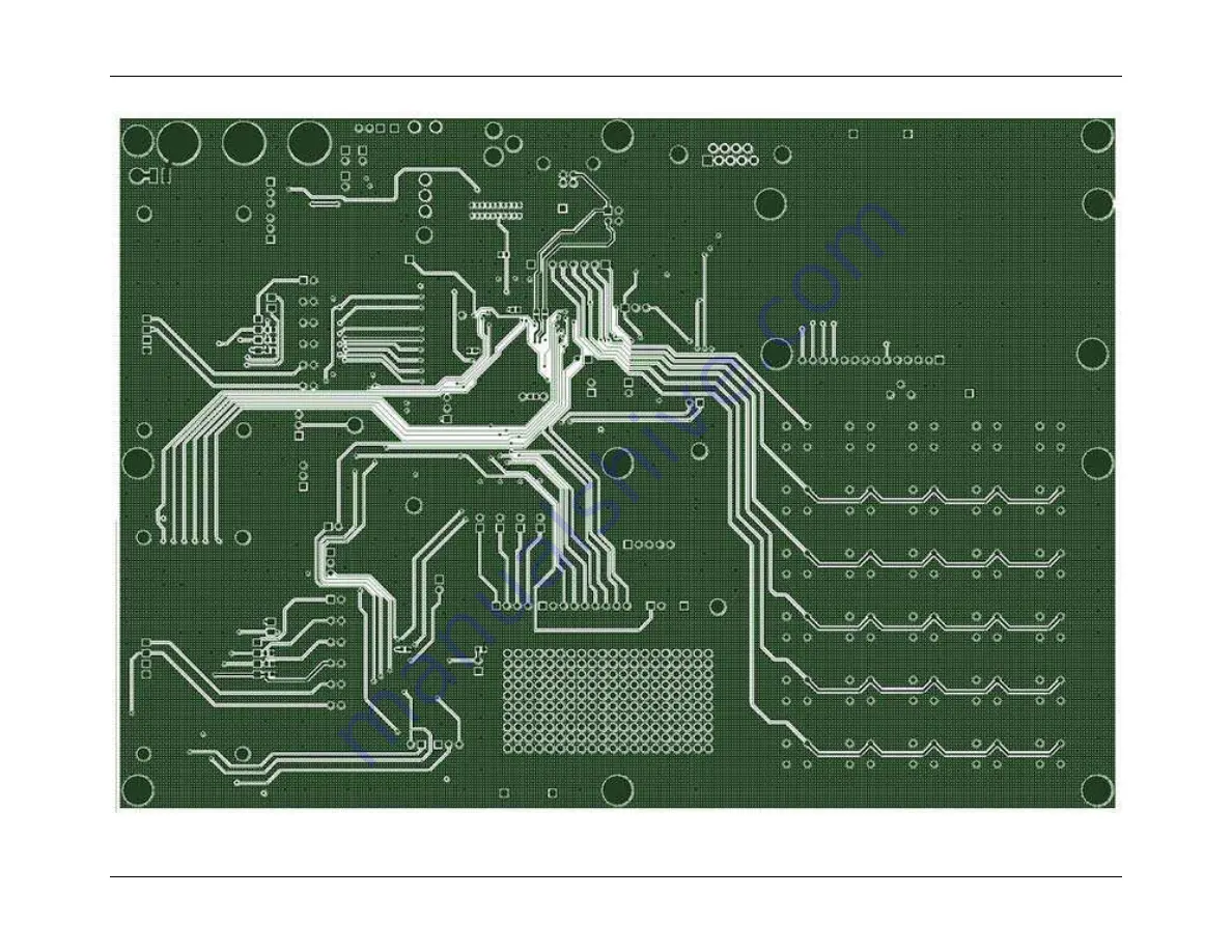
Figure 14: 73S1215F Evaluation Board Bottom Signal Layer
Downloaded from:
http://www.datasheetcatalog.com/
Page 1: ...Simplifying System Integration TM 73S1215F Evaluation Board User Guide August 17 2009 Rev 1 8 UG_1215F_039 Downloaded from http www datasheetcatalog com...
Page 2: ...property of their respective owners Teridian Semiconductor Corporation makes no warranty for the use of its products other than expressly contained in the Company s warranty detailed in the Teridian S...
Page 3: ...stration Software Installation 11 3 1 1 Installation on Windows XP 11 3 1 2 Driver and Software Installation on a Linux System 12 3 2 Frequently Asked Questions 12 4 Evaluation Board Hardware Descript...
Page 4: ...Board Top View Silkscreen 22 Figure 10 73S1215F Evaluation Board Bottom View Silkscreen 23 Figure 11 73S1215F Evaluation Board Top Signal Layer 24 Figure 12 73S1215F Evaluation Board Middle Layer 1 G...
Page 5: ...ammed to run any of the Teridian turnkey applications or a user developed custom application Teridian provides its USB CCID application preloaded on the board and an EMV testing application on the CD...
Page 6: ...73S1215F Evaluation Board see Figure 1 includes the following USB 2 0 full speed interface RS 232 interface Dual smart card interface ICE Programmer interface 2 line x 16 character LCD module 6 x 5 k...
Page 7: ...red devices In this case the board main switch S1 has no effect When the board is powered from the USB bus the application is bus powered and the embedded application must be designed for this The USB...
Page 8: ...tem pod has a ribbon cable that must be directly attached to connector J11 Signum Systems offers different pod options depending on user needs The standard pod allows users to perform typical emulator...
Page 9: ...tems ADM51 in circuit emulator or the TSC Flash Programmer Model TFP2 provided by Teridian Loading Code with the In Circuit Emulator If firmware exists in the 73S1215F flash memory the memory must be...
Page 10: ...Guide UG_1215F_039 10 Rev 1 8 Figure 4 Emulator Window Showing RESET and ERASE Buttons Figure 5 Emulator Window Showing Erased Flash Memory and File Load Menu RESET BUTTON ERASE BUTTON Downloaded from...
Page 11: ...rades Follow these steps to install the software on a PC running Windows XP Extract 12xxF CCID DFU Vy yy Release zip where y yy is the latest version of the firmware release o Create an install direct...
Page 12: ...power applied to the board 2 Control Panel System Hardware Device Manager Smart Card Readers shows Teridian Semiconductors USB CCID Smart Card Reader And there is no yellow or red X 3 Smart Card Servi...
Page 13: ...c drivers ifd ccid bundle Contents Info plist in an editor and set ifdLogLevel to 7 Save the change Then run the command pcscd f d in a console Now pcscd runs in foreground and should display many mes...
Page 14: ...se a jumper must be inserted in this header to connect the 3 3 V power supply of the board to the VDD pins of the 73S1215F This jumper can be replaced by a A mA meter to measure the actual current dra...
Page 15: ...SR7 interrupt for other uses The analog input can be set up to use the compare to detect when the USB cable is inserted removed 11 P1 No Connect DB9 RS232 female socket This socket allows connection o...
Page 16: ...to the LED pins of the 73S1215F This jumper can be replaced by a A mA meter to measure the actual current drawn by the LED outputs of the 73S1215F 20 JP12 Inserted Jumper 73S8010R VPC connect Inserti...
Page 17: ...cted to the daughter card pin USR6 This allows the SCL line to connect to an SCL pin on a 73S8010R daughter card 28 JP10 Not Inserted Jumper USR6 AUX1 select This jumper allows the on board 73S8010 AU...
Page 18: ...24 R33 Jumper resistors These jumper resistors will configure the board for a 73S1215F device U3 should not be populated 35 U3 73S8009 See item 34 36 JP1 VOUT Jumper power supply selection 2 This jump...
Page 19: ...User Guide Rev 1 8 19 1 2 3 5 7 9 11 12 13 4 6 8 10 14 15 25 23 21 19 16 22 20 18 17 24 34 32 30 37 36 35 33 31 29 28 27 26 Figure 7 73S1215F Evaluation Board Jumper Switch and Module Locations Downlo...
Page 20: ...he card connectors Contains the card signals VCC1 RST1 CLK1 C81 and C41 Each contact has its own ground pin on the header TP11 to TP17 GND Ground test points Can be used for grounding of lab equipment...
Page 21: ...T3IN 22 T4IN 19 T5IN 17 R1OUTBF 16 R1OUT 21 R2OUT 20 R3OUT 18 GND 2 MBAUD 15 SHDNB 14 ENB 13 R3IN 11 R2IN 9 R1IN 8 T1OUT 5 T2OUT 6 T3OUT 7 T4OUT 10 T5OUT 12 V 4 V 27 VCC 26 U7 MAX3237CAI ACTIVE HIGH R...
Page 22: ...73S1215F Evaluation Board User Guide UG_1215F_039 22 Rev 1 8 4 4 PCB Layouts Figure 9 73S1215F Evaluation Board Top View Silkscreen Downloaded from http www datasheetcatalog com...
Page 23: ...UG_1215F_039 73S1215F Evaluation Board User Guide Rev 1 8 23 Figure 10 73S1215F Evaluation Board Bottom View Silkscreen Downloaded from http www datasheetcatalog com...
Page 24: ...73S1215F Evaluation Board User Guide UG_1215F_039 24 Rev 1 8 Figure 11 73S1215F Evaluation Board Top Signal Layer Downloaded from http www datasheetcatalog com...
Page 25: ...UG_1215F_039 73S1215F Evaluation Board User Guide Rev 1 8 25 Figure 12 73S1215F Evaluation Board Middle Layer 1 Ground Plane Downloaded from http www datasheetcatalog com...
Page 26: ...73S1215F Evaluation Board User Guide UG_1215F_039 26 Rev 1 8 Figure 13 73S1215F Evaluation Board Middle Layer 2 Supply Plane Downloaded from http www datasheetcatalog com...
Page 27: ...UG_1215F_039 73S1215F Evaluation Board User Guide Rev 1 8 27 Figure 14 73S1215F Evaluation Board Bottom Signal Layer Downloaded from http www datasheetcatalog com...
Page 28: ...C1608X5R1A105K TDK Corporation 9 9 C22 C23 C24 C25 C38 C39 C40 C41 C42 22 pF 603 PCC220ACVCT ND ECJ 1VC1H220J Panasonic 10 1 C43 1000 pF 603 PCC2151CT ND ECJ 1VC1H102J Panasonic 11 1 D1 MBR0520L SOD 1...
Page 29: ...33 2 R12 R13 3 k 603 P3 0KGCT ND ERJ 3GEYJ302V Panasonic 34 1 R34 1 M 603 P1 0MGCT ND ERJ 3GEYJ106V Panasonic 35 1 S1 POWER_SWITCH POW_SW EG2363 ND 100SP1T2B4M6RE E Switch 36 30 S2 S3 S4 S5 S6 S7 S8...
Page 30: ...EADER 5 5 x 1 pin S1011E 36 ND PBC36SAAN Sullins Electronics 49 1 U1 LM1117DT 5 0 TO 252 3 LM1117DT 5 0 ND LM1117DT 5 0 National Semiconductor 50 1 U2 LP2985 LP2985IM5 3 3CT ND LP2985IM5 3 3 National...
Page 31: ...10uF R10 10k R8 10 C43 1000pF Figure 15 External Components for RESET 4 6 2 Oscillators The 73S1215F offers two oscillators see Figure 16 one for the primary system clock and the other for an RTC 32 K...
Page 32: ...ns 4 6 4 USB Interface The USB interface on the 73S1215F requires few external components for proper operation Two serial resistors of 24 1 are needed to provide proper impedance matching for the USB...
Page 33: ...se card event The same holds true for the PRES input except a pull up resistor is utilized as the logic is inverted from the PRES input The smart card interface layout is important The following guide...
Page 34: ...ata Sheet 73S1215F Evaluation Board Quick Start Guide TSC Flash Programmer Model TFP2 User s Manual 7 Contact Information For more information about Teridian Semiconductor products or to check the ava...
Page 35: ...o C38 C42 to the schematic and BOM 1 3 November 9 2007 Added emulator usage and schematic descriptions 1 4 January 3 2007 Removed capacitor and pull up resistors from the ICE interface 1 5 March 5 200...
Page 36: ...This datasheet has been downloaded from www DatasheetCatalog com Datasheets for electronic components Downloaded from http www datasheetcatalog com...