background image

First Edition • Second Printing


Operator's Manual


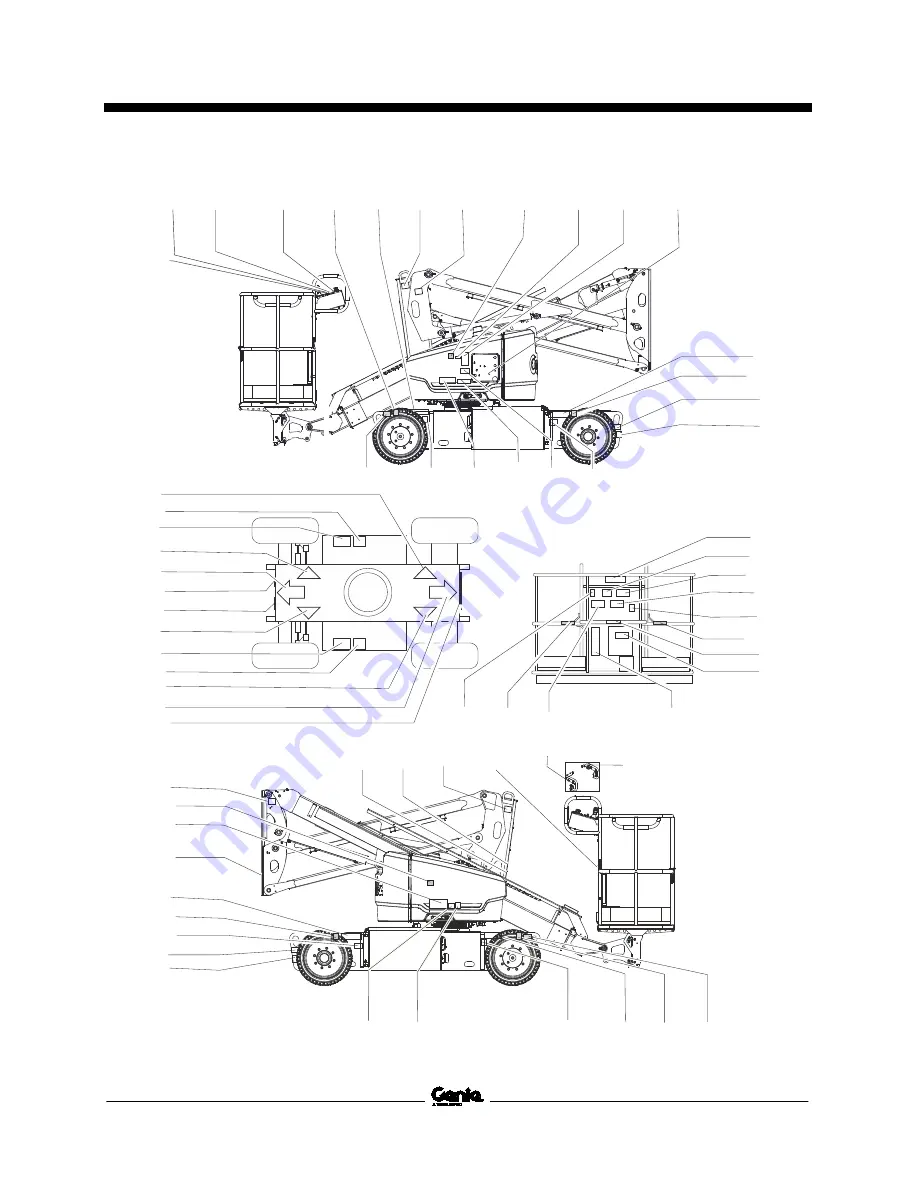
Inspections 


Part No. 1257143GT


Z

®

-33 

37 


27204

27206

114334

133286

27207

27207

114252

114345

114345

82481

27205

82481

27206

114252

82487

97815

114249

114252

114249

133067

82487

1257156

1258982

1258499

1258982

1258982

1281175

114249

133067

1258499

1261930

1257157

1258500

72086

52475

72086 1258982

72086
52475

72086

52475

114249 52475 72086

1258501

133067

219958

*28174 

*28235

1281175

219956

114248

1281175

1281175

72086

1261869

1262127

1262127

44981

114427

1272242

*28174 

*28235 44981

1263542

1263542

1286362

1278982

1278542

1261929

72867

Summary of Contents for Z-33

Page 1: ...Operator s Manual Z 33 DC Power from Z3318M 2801 CE with Maintenance Information Original Instructions First Edition Second Printing Part No 1257143GT Front Matter...

Page 2: ...Contents Introduction 1 Symbol and Hazard Pictorials Definitions 5 General Safety 7 Personal Safety 10 Work Area Safety 11 Legend 19 Controls 20 Inspections 25 Operating Instructions 38 Transport and...

Page 3: ...rial number stamped on chassis Intended Use and Familiarization Guide The intended use of this machine is to lift personnel including tools and materials to an aerial work site Before operating the ma...

Page 4: ...ment Platform level Primary boom extend retract Primary boom up down Secondary boom up down Turntable rotate Sequential functions and movement Drive and steer Interlocked functions Elevated drive spee...

Page 5: ...our machine be sure to comply with the action indicated in a respective bulletin Contacting the Manufacturer At times it may be necessary to contact Genie When you do be ready to supply the model numb...

Page 6: ...ite regulations You read understand and obey all applicable governmental regulations You are properly trained to safely operate the machine Safety Sign Maintenance Replace any missing or damaged safet...

Page 7: ...rd Collision hazard Runaway hazard Tip over hazard Tip over hazard Raise platform on firm level surface Electrocution hazard Maintain required clearance Color coded direction arrows Maximum capacity W...

Page 8: ...ary 2 Lower secondary 3 Retract primary Platform downhill 1 Retract primary 2 Lower secondary 3 Lower primary Wheel load Lanyard anchorage points Replace tires with tires of same specification Voltage...

Page 9: ...First Edition Second Printing Operator s Manual General Safety Part No 1257143GT Z 33 7 General Safety...

Page 10: ...Operator s Manual First Edition Second Printing General Safety 8 Z 33 Part No 1257143GT...

Page 11: ...First Edition Second Printing Operator s Manual General Safety Part No 1257143GT Z 33 9...

Page 12: ...cupants must wear a safety belt or harness in accordance with governmental regulations Attach the lanyard to the anchor provided in the platform Operators must comply with employer job site and govern...

Page 13: ...the machine if it contacts energized power lines Personnel on the ground or in the platform must not touch or operate the machine until energized power lines are shut off Do not operate the machine du...

Page 14: ...oom 3 Retract the primary boom If the tilt alarm sounds with the platform downhill 1 Retract the primary boom 2 Lower the secondary boom 3 Lower the primary boom Do not raise the boom when wind speeds...

Page 15: ...em can increase the weight in the platform and the surface area of the platform or the load Do not place or attach fixed or overhanging loads to any part of this machine Do not place ladders or scaffo...

Page 16: ...perating Instructions section Fall Hazards Occupants must wear a safety belt or harness in accordance with governmental regulations Attach the lanyard to the anchor provided in the platform Do not sit...

Page 17: ...ernmental rules regarding use of personal protective equipment Observe and use the color coded direction arrows on the platform controls and drive chassis for drive and steer functions Do not lower th...

Page 18: ...ocations or locations where potentially flammable or explosive gases or particles may be present Damaged Machine Hazards Do not use a damaged or malfunctioning machine Conduct a thorough pre operation...

Page 19: ...hat may cause sparks Component Damage Hazard Do not use any battery charger greater than 48V to charge the function batteries Both battery packs must be charged together Disconnect the battery pack pl...

Page 20: ...rated platform capacity and must be subtracted from the total platform load The contact alarm assembly weighs 10 lbs 4 5 kg Be sure the contact alarm is securely installed Lockout After Each Use 1 Se...

Page 21: ...nd 1 Foot switch 2 Manual storage container 3 Sliding mid rail 4 Lanyard anchorage points 5 Platform 6 Platform controls 7 Primary boom 8 Secondary boom 9 Ground controls 10 Power to charger between t...

Page 22: ...rescue an incapacitated person in the platform When the ground control station is selected the platform controls are inoperable including the E stop switch 1 Platform level switch 2 Turntable rotate s...

Page 23: ...ht Light flashing indicates the platform is overloaded and no functions will operate Remove weight until the light goes off 6 Key switch for platform off ground selection Turn the key switch to the pl...

Page 24: ...l indicator light 6 Red Emergency Stop button 7 Proportional control handle for drive function and thumb rocker for steer function 8 Drive enable indicator light 9 LCD display 10 Drive enable switch 1...

Page 25: ...l out the red Emergency Stop button to the on position to operate the machine 7 Proportional control handle for drive function and thumb rocker for steer function Move the control handle in the direct...

Page 26: ...handle to the right and the turntable will rotate to the right Move the control handle to the left and the turntable will rotate to the left 13 Thumb rocker switch for primary boom extend retract func...

Page 27: ...ch work shift The inspection is designed to discover if anything is apparently wrong with a machine before the operator performs the function tests The pre operation inspection also serves to determin...

Page 28: ...zed modifications Electrical components wiring and electrical cables Hydraulic hoses fittings cylinders and manifolds Hydraulic tank Drive and turntable motors and drive hubs Wear pads Tires and wheel...

Page 29: ...the machine as it was intended Function Test Fundamentals The function tests are designed to discover any malfunctions before the machine is put into service The operator must follow the step by step...

Page 30: ...ess and hold the function enable button and activate each boom and platform function toggle switch Result All boom and platform functions should operate through a full cycle The descent alarm should s...

Page 31: ...down the foot switch and test each machine function Result No functions should operate Test Machine Functions 21 Press down the foot switch 22 Activate each machine function control handle or toggle s...

Page 32: ...ssis then come to an abrupt stop Note The brakes must be able to hold the machine on any slope it is able to climb Test the Drive Enable System 29 Press down the foot switch and lower the boom to the...

Page 33: ...etract and lower the boom to the stowed position If the drive speed with the primary or secondary boom raised or the primary boom extended exceeds 0 79 ft 24 cm per second immediately tag and remove t...

Page 34: ...ry boom to the stowed position or drive in the opposite direction Result The machine should drive 57 Return to level ground and extend the primary boom approximately 1 6 ft 0 5 m 58 Drive the machine...

Page 35: ...rive the machine onto a slope where the chassis roll angle is greater than 2 5 Result The machine should stop once the machine reaches 2 5 of chassis tilt and the alarm should sound at the platform co...

Page 36: ...hine horn will sound 79 Insert the actuator into the switch socket Result The lights and horn will turn off 80 Activate the foot switch by pressing the foot switch down and press on the contact alarm...

Page 37: ...or determine if the workplace is suitable for safe machine operation It should be performed by the operator prior to moving the machine to the workplace It is the operator s responsibility to read and...

Page 38: ...d Limit Switches 3 114334 Label Electrocution Hazard Plug 1 114345 Label Tip over Hazard Batteries 2 114427 Label Screen Protector 1 133067 Label Electrocution Hazard 3 133286 Label Power to Charger 2...

Page 39: ...4249 114252 114249 133067 82487 1257156 1258982 1258499 1258982 1258982 1281175 114249 133067 1258499 1261930 1257157 1258500 72086 52475 72086 1258982 72086 52475 72086 52475 114249 52475 72086 12585...

Page 40: ...machine operation It is the operator s responsibility to follow all the safety rules and instructions in the operator s manual Using the machine for anything other than lifting personnel along with t...

Page 41: ...ed Emergency Stop button to the on position 3 Press down the foot switch when using the controls from the platform 4 Simultaneously hold the auxiliary power switch on and activate the desired function...

Page 42: ...kings on the control panel To Steer 1 Press down the foot switch 2 Turn the steer wheels with the thumb rocker switch located on the top of the control handle Use the color coded direction arrows on t...

Page 43: ...the non steer wheels To determine the slope grade Measure the slope with a digital inclinometer OR use the following procedure You will need carpenter s level straight piece of wood at least 1 m long...

Page 44: ...as moved just past either non steer wheel and the drive function has been interrupted To drive hold the drive enable switch to either side and slowly move the drive control handle off center Be aware...

Page 45: ...hill 1 Lower the primary boom 2 Lower the secondary boom 3 Retract the primary boom If the tilt alarm sounds with the platform downhill 1 Retract the primary boom 2 Lower the secondary boom 3 Lower th...

Page 46: ...warning lights When the contact alarm cable is tripped the lift and drive functions are disabled at the platform The audio and visual warnings will activate alerting others that assistance may be need...

Page 47: ...sure the batteries are connected before charging the batteries 2 Open the battery compartment The compartment should remain open for the entire charging cycle Standard Batteries 1 Remove the battery...

Page 48: ...use the battery acid to overflow during charging Neutralize battery acid spills with baking soda and water 3 Install the battery vent caps 4 Charge the battery 5 Check the battery acid level when the...

Page 49: ...nie lifts are very heavy relative to their size See the serial label for the machine weight See the inspections section for the serial label location Be sure the turntable is secured with the turntabl...

Page 50: ...the off position and remove the key before transporting Inspect the entire machine for loose or unsecured items Securing the Chassis Use chains of ample load capacity Use a minimum of 4 chains or str...

Page 51: ...stand the machine weight See the serial label for the machine weight Lifting Instructions Fully lower and retract the boom Fully lower the jib Remove all loose items on the machine Use the turntable r...

Page 52: ...ning of a maintenance procedure it conveys the meaning below Indicates that tools will be required to perform this procedure Indicates that new parts will be required to perform this procedure Check t...

Page 53: ...e connections are tight and free of corrosion 3 Be sure that the battery hold down brackets are in place and secure Standard Batteries 4 Remove the battery vent caps 5 Check the battery acid level of...

Page 54: ...t torque dry 125 ft lbs 169 5 Nm Lug nut torque lubricated 94 ft lbs 127 5 Nm Ambient operating temperature 20 F to 120 F 29 C to 49 C Airborne noise emissions Sound pressure level at ground workstati...

Page 55: ...3GT Z 33 53 Range of Motion Chart Max Height Max Reach 1 35 ft 10 6 m 9 0 ft 0 m 2 30 ft 9 1 m 10 5 ft 1 5 m 3 25 ft 7 6 m 11 10 ft 3 m 4 20 ft 6 1 m 12 15 ft 4 6 m 5 15 ft 4 6 m 13 20 ft 6 1 m 6 10 f...

Page 56: ...SO 3744 internal combustion engine only Test Report This machine has been tested and passed the following categories prior to entering the market 1 BRAKES Brakes working properly in forward and revers...

Page 57: ...005 3525 2015 98 under consideration of Annex V and designated standard EN ISO 3744 internal combustion engine only Test Report This machine has been tested and passed the following categories prior t...

Page 58: ......

Reviews: