October 2021
Service and Repair Manual
Platform Controls
Part No. 1268515GT
Z
®
-34/22 Bi-Energy
15
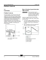
3 Locate the diode between the black/red wire
from the boom function speed controller and
the white/red wire. Disconnect the white/red
wire from the diode on the black/red wire.
4 Connect the negative lead from a multimeter
set to measure amperage to the wire
connector of the white/red wire. Connect the
positive lead of the multimeter to the diode on
the black/red wire.
5 Turn the boom function speed controller to the
creep position.
6 Set the threshold: Press down the foot switch
and move the primary boom toggle switch to
the up position. Adjust the amperage to
0.28A. Turn the threshold trimpot adjustment
screw clockwise to increase the amperage or
counterclockwise to decrease the amperage.
7 Turn the boom function speed controller to the
9 position.
8 Set the max out: Press down the foot switch
and move the primary boom toggle switch to
the down position. Adjust the amperage to
0.65A. Turn the max out trimpot adjustment
screw clockwise to increase the amperage or
counterclockwise to decrease the amperage.
9 Start a timer and simultaneously press down
the foot switch and move the primary boom
toggle switch in the down direction. Note how
long it takes to reach 0.65A.
10 Set the ramp rate: Turn the ramp rate trimpot
to obtain a 2 second delay from 0 to 0.65A.
Turn the trimpot clockwise to increase the
time or counterclockwise to decrease the
time.
11 Disconnect the leads from the multimeter and
connect the white/red wire to the diode on the
black/red wire.
Boom function speed controller specifications
Threshold
(controller turned to creep)
0.28A
Max out
(controller turned to 9)
0.65A
Ramp rate
2 seconds
Summary of Contents for Genie Z-34/22
Page 63: ...October 2021 Service and Repair Manual Manifolds Part No 1268515GT Z 34 22 Bi Energy 51 ...
Page 89: ...October 2021 Service and Repair Manual 77 Electrical Schematic ANSI CSA from SN Z34F 12066 ...
Page 92: ...Service and Repair Manual October 2021 80 Electrical Schematic ANSI CSA from SN Z34F 12066 ...
Page 97: ...October 2021 Service and Repair Manual 85 PBOX Wiring Diagram ANSI CSA from SN Z3414 9686 ...
Page 103: ...October 2021 Service and Repair Manual 91 Electrical Schematic CE AS from SN Z34F 12066 ...
Page 106: ...Service and Repair Manual October 2021 94 Electrical Schematic CE AS from SN Z34F 12066 ...
Page 114: ...Service and Repair Manual October 2021 102 Power Cable Wiring Diagram from SN Z3414 9686 ...
Page 115: ...October 2021 Service and Repair Manual 103 Drive Contactor Panel Wiring Diagram ...
Page 118: ...Service and Repair Manual October 2021 106 Manifold and Limit Switch Wiring Diagram ...
Page 119: ...October 2021 Service and Repair Manual 107 LVI BCI Option Wiring Diagram ...
Page 122: ...Service and Repair Manual October 2021 110 Charger Interlock Option ...
Page 123: ...October 2021 Service and Repair Manual 111 Engine Wiring Diagram ...
Page 126: ...Service and Repair Manual October 2021 114 Contact Alarm Option from SN Z34F 12066 ...
Page 127: ...October 2021 Service and Repair Manual 115 Fuel Level Sensor Option from SN Z34F 12066 ...
Page 129: ...October 2021 Service and Repair Manual 117 Hydraulic Schematic ...
Page 131: ......


