background image

Operator's Manual Supplement


Second Edition • First Printing


Safety Rules 


Lighting Technicians and Studio Grips Supplement


Part No. 1314078GT 


LDFs hung from the platform guard rail must 
not be rigidly attached in any manner that could 
cause or impose a side or vertical load from 
wind or contact with adjacent objects greater 
than the rated side load posted at the entrance 
to the platform. 


Attachment of LDFs and rope to the platform 
shall be accomplished in a manner that does 
not cause a tip-over hazard due to a side or 
vertical force that could result in the machine 
becoming unstable. 


Do not alter the guard rail system by drilling, 
welding, crushing, damaging or making any 
other modifications that compromise the 
strength of the guard rail when attaching movie 
production equipment. 


The entrance to the platform, the platform 
controls, including the foot switch and the 
emergency stop button, the lanyard anchorage 
points, the platform decals and instruction 
container must remain accessible when movie 
production equipment is attached to the 
platform. 


Operators must not gain access to or exit the 
platform by means of walking or climbing on 
the boom or lift structure or by attaching a rope 
or a hanging ladder from the platform or its 
supporting structure. Access to and exit from 
the platform shall be accomplished at ground 
level only. 


The combined weight of platform attachments, 
power supply cables, mounting hardware, 
platform occupant(s), tools and equipment 
must in all cases remain less than the 
maximum rated platform capacity for both 
personnel lifting and material only lifting 
applications. Use the platform capacity 
reduction chart found in this supplement to 
determine allowable platform load. 


The number and size of attachments must be 
limited by consideration of the maximum 
allowable wind speed and the surface area of 
platform attachments. Use the wind speed 
chart found in this supplement to determine 
maximum allowable wind speed. 


Information regarding the attachment of LDFs 
and lighting and camera equipment shall be 
supplied only to trained union members. 
Operators must be familiar with these 
supplemental instructions and warnings before 
they are allowed to operate any Genie boom 
that is approved for this application. 


The grips panel must be mounted in a way that 
the center of gravity of the frame is always 
located below the platform floor. 


An accurate wind speed measuring device, 
such as an anemometer, must be used to 
measure the wind speed if the wind speed 
charts are to be used. 


Summary of Contents for Genie S-45 Trax

Page 1: ...fered by qualified trainers in aerial work platform operation combined with use of set lighting camera equipment and light diffusion frames Users of this manual must be trained as Genie aerial work platform operators Failure to receive training and to use the information contained in this supplement and in the operator s manual may result in death or serious injury Original Instructions Second Edi...

Page 2: ...l if the supplement is used in a manner that creates a safety concern Manufacturer Terex Global GmbH Bleicheplatz 2 Schaffhausen 8200 Switzerland EU Authorized representative Genie Industries B V Boekerman 5 4751 XK OUD GASTEL The Netherlands UK Authorized representative Genie UK Limited The Maltings Wharf Road Grantham NG31 6BH UK Contents Introduction 1 Important Information 3 Safety Rules 5 Win...

Page 3: ...cific training do not deviate from the requirements of the standard Genie Operator s Manual for use of Genie equipment Strict compliance with this Supplemental Manual as well as Genie s standard Operator s Manual and Manual of Responsibilities ANSI markets along with completion of specialized training is essential to safe operation of the Approved Models as set forth in this supplement Approved Mo...

Page 4: ...requirements that must be followed by specifically trained operators to enable them to use the Approved Models in the manner set forth in this Supplemental Manual Proof of Training and Records Retention Qualified trainers shall provide proof of training to all successful trainees The document evidencing training shall include the following information The name of the person operator being trained ...

Page 5: ...ication All operating instructions and warnings contained in the Operator s Manual Safety Manual ANSI markets and Manual of Responsibilities ANSI markets and on decals found on the particular Genie aerial lift must be followed The aerial lift must be operated only on a firm level surface Operators must be trained and be able to demonstrate proficiency in the operation of the specific model of Geni...

Page 6: ... or lift structure or by attaching a rope or a hanging ladder from the platform or its supporting structure Access to and exit from the platform shall be accomplished at ground level only The combined weight of platform attachments power supply cables mounting hardware platform occupant s tools and equipment must in all cases remain less than the maximum rated platform capacity for both personnel ...

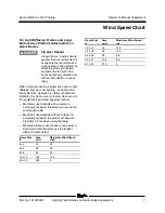
Page 7: ... frames or set lighting is attached to a boom platform operation in windy conditions is limited by the frame size or total surface area of the equipment and wind speed as follows Machines used outside with a device to accurately measure the wind can use the full wind speed table Machines used outside without a device to accurately measure the wind must assume 28 mph 12 5 ms when using the table Ma...

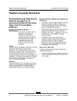
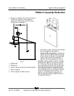
Page 8: ...is mounted from the center of the platform the greater the reduction in platform capacity Definition Center of Gravity C G The balance point of an object The point at which the entire weight of an object is concentrated so that if the object is suspended from that point it will be balanced Reduce platform capacity according to the following Attachment of power supply cables to the boom reduces the...

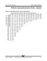
Page 9: ... the platform Personnel lifting applications Subtract this number from the maximum platform capacity of the machine as defined in the appropriate machine operator s manual and decals to determine the remaining platform capacity Example Lighting equipment and the mounting bracket used to attach it to the guard rail weigh 167 lbs 76 kgs Their center of gravity balance point is located at 35 in 0 8 m...

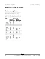
Page 10: ...ted and restricted platform capacities refer to the Range of Motion Charts in the Operators Manual on your machine Model Reduction chart Unrestricted Capacity Rating Restricted Capacity Rating lbs kgs lbs kgs Z 34 22 500 227 Z 45 XC 660 300 Z 45 DC FE 660 300 Z 60 DC FE 500 227 Z 80 60 500 227 S 45 XC 660 300 1000 454 S 45 TRAX 660 300 1000 454 S 65 XC 660 300 1000 454 S 65 TRAX 660 300 1000 454 S...

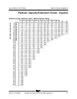
Page 11: ...96 108 120 132 144 156 Total Weight of Equipment lbs 50 Platform Capacity Reduction lbs 50 59 67 83 99 116 132 148 164 181 197 213 229 75 75 88 100 125 149 173 198 222 246 271 295 320 344 100 100 117 134 166 199 231 264 296 329 361 394 426 459 125 125 147 167 208 248 289 330 370 411 451 492 150 150 176 201 249 298 347 395 444 493 175 175 206 234 291 348 404 461 200 200 235 267 332 397 462 225 225 ...

Page 12: ...148 164 181 197 213 229 75 75 88 100 125 149 173 198 222 246 271 295 320 344 100 100 117 134 166 199 231 264 296 329 361 394 426 459 125 125 147 167 208 248 289 330 370 411 451 492 533 573 150 150 176 201 249 298 347 395 444 493 542 590 639 175 175 206 234 291 348 404 461 518 575 632 200 200 235 267 332 397 462 527 592 657 225 225 264 301 374 447 520 593 250 250 294 334 415 497 578 659 275 275 323...

Page 13: ...201 249 298 347 395 444 493 542 590 639 688 175 175 206 234 291 348 404 461 518 575 632 689 746 802 200 200 235 267 332 397 462 527 592 657 722 787 852 917 225 225 264 301 374 447 520 593 666 739 812 886 959 250 250 294 334 415 497 578 659 740 821 903 984 275 275 323 368 457 546 636 725 814 904 993 300 300 352 401 498 596 693 791 888 986 325 325 382 434 540 646 751 857 962 350 350 411 468 582 695 ...

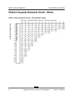
Page 14: ...1 2 1 5 1 8 2 1 2 4 2 7 3 0 3 4 3 7 4 0 Total Weight of Equipment kg 23 Platform Capacity Reduction kg 23 27 30 38 45 52 60 67 75 82 89 97 104 34 34 40 45 57 68 79 90 101 112 123 134 145 156 45 45 53 61 75 90 105 120 134 149 164 179 193 208 57 57 67 76 94 113 131 149 168 186 205 223 68 68 80 91 113 135 157 179 201 224 79 79 93 106 132 158 183 209 91 91 107 121 151 180 210 102 102 120 136 170 203 1...

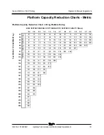
Page 15: ... 45 52 60 67 75 82 89 97 104 34 34 40 45 57 68 79 90 101 112 123 134 145 156 45 45 53 61 75 90 105 120 134 149 164 179 193 208 57 57 67 76 94 113 131 149 168 186 205 223 242 260 68 68 80 91 113 135 157 179 201 224 246 268 290 79 79 93 106 132 158 183 209 235 261 287 91 91 107 121 151 180 210 239 269 298 102 102 120 136 170 203 236 269 113 113 133 152 188 225 262 299 125 125 146 167 207 248 288 136...

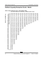
Page 16: ... 287 312 338 364 91 91 107 121 151 180 210 239 269 298 328 357 386 416 102 102 120 136 170 203 236 269 302 335 369 402 435 113 113 133 152 188 225 262 299 336 373 409 446 125 125 146 167 207 248 288 329 369 410 450 136 136 160 182 226 270 315 359 403 447 147 147 173 197 245 293 341 389 437 159 159 186 212 264 315 367 419 170 170 200 227 283 338 393 448 181 181 213 243 301 360 419 193 193 226 258 3...

Page 17: ......

Reviews: