


Self-Balancing Robot
User Guide
12
www.terasic.com
July 12, 2018
15:0
RO
Counter
(For
Read)
Read
Counter
value for Motor
output pules
Base Addr + 1
31:30
RW
Unuse
-
1
RW
count_en
Enable
Motor
pulse counter
Base Addr + 2
31:16
WO
Unused
-
15:0
WO
Couter
(For
Write)
Set
Counter
vaule
⚫
⚫
I
I
P
P
C
C
o
o
d
d
e
e
D
D
e
e
s
s
c
c
r
r
i
i
p
p
t
t
i
i
o
o
n
n
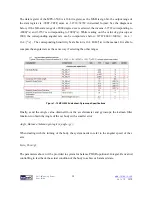
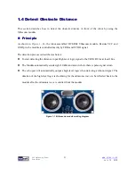
There is a submodule code TERAISC_AB_DECODER.v in motor_measure.v IP, this submodule
can detect phase A and phase B signals from the motor, and according the different phases, the
submodule can figure out whether the rotation direction is clockwise or counterclockwise. The
direction result will output to DO_DIRECT port and the rotation pulse will output to DO_PULSE
port. Then these two signal will pass to the motor_measure.v IP.
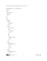
TERAISC_AB_DECODER u_decoder
(
.DI_SYSCLK(clk),
.DI_PHASE_A(phase_AB[0]),
.DI_PHASE_B(phase_AB[1]),
.DO_PULSE(conter_pulse),
.DO_DIRECT(direction)
);
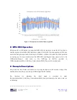
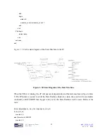
Please refer to below code list in below, the motor_measure IP has a 16bit
Counter
(initial value is
16'h8000) register, which is enabled only if the "
count_en
" register is set to 1. In the beging When
the motor rotates clockwise (direction = 1), The
Counter
register will count from the initial value
and increase by the number of pulses returned from the motor; If the motor rotates
counterclockwise, the
Counter
register also will decrement with the number of pulses returned by
the motor. The system will periodically read the value of this
Counter
register to acquire the current


