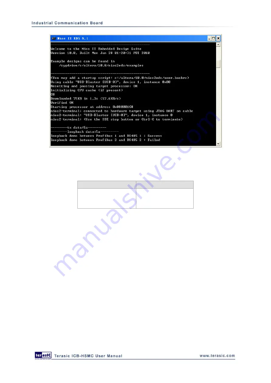
Figure 5-5 Test results on the prompt window
Table 5-1 Loopback test result on HEXs for RS-485
Test Pass Info.
Test failed info.
S-<test data*>
FAIL
*
test data represents the value set by SW15-8 or SW7-0.
29
5.4
5.4
CAN
Loopback
Test
CAN Loopback Test
This demonstration illustrates how to construct a communication loop between two CAN interfaces
where one initiates the data transfer and the other receives data then sends it back to the loop.
SW7-0 is used to set up the transmit data contents. The data loopback flow for CAN is the same as
RS-485. In this demonstration, the Nios II processor in the FPGA on the DE2-115 board takes
charge of the control work and gives the test result information. The block diagram of the CAN
loopback test is as shown in
.


