•
Power
(red) – this flashes when the power supply is turned on;
•
Busy
(yellow) – this LED indicates that someone is connected to the controller through
web interface;
•
Link
(green) – this LED is located on the Ethernet connector. It indicates that the device is
connected to the network ;
•
Act
(yellow) – this LED is located on the Ethernet connector. It flashes when activity is
detected on the network.
6.
Example Application
6.1
Remote control
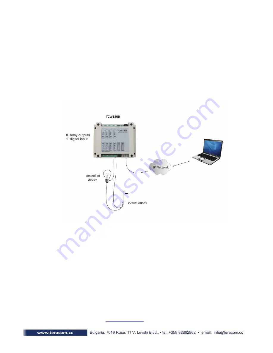
The controlled device is connected in series with the relay contacts. User can operate
TCW180B
using a web browser or SNMP application. The relays can be managed independently of
each other.
7.
Installation
Please follow the steps below for proper installation :
1.
Mount the controller in a dry and ventilated place.
2.
Connect the Ethernet port to a 10/100MB Ethernet network. For direct connection to a PC
use a “crossover” cable.
3.
Connect the I/O pins of the controller according to the required application.
4.
Connect the power supply.
If the red LED blinks, the power supply is OK. By default
TCW180B
comes with the following
network settings:
IP address:
192.168.1.2,
Subnet Mask:
255.255.255.0,
Default Gateway:
192.168.1.1
Communication with
TCW180B
can be established by assigning a temporary IP address to the
computer. This address should be in the same network (for example 192.168.1.3). To get access to the
web interface, you should type
http://192.168.1.2
into the browser.


