background image

IB 340770 (08--2005)

5

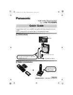
9. Route the loose end of the 3’ braided hose (35)

through the scrub head lift assembly and to the

solution manifold. Refer to Fig. 8.

21

35

FIG. 8

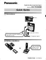
10. Use a hex screw (20) to attach another spring

holder clip (19) to the scrub head lift assembly.

Refer to Fig. 9.

19

18

35

17

FIG. 9

11. Cut the plug from the end of the solution

manifold hose. Refer to Fig. 19.

12. Use a hose clamp (18) to install a check valve

(17) onto the solution manifold. Refer to Fig. 9

and Fig. 19.

13. Use a hose clamp (18) to install the other end of

the 3’ braided hose (35) onto the check valve

(17). Refer to Fig. 9 and Fig. 19.

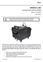
14. Insert the rubber grommet (42) into the hole in

the frame of the machine. Refer to Fig. 10.

Insert the rubber grommet

(42) into this hole.

Frame

FIG. 10

15. Use the clevis pins (A), (B), (C), and (D) to

reinstall the scrub head lift assembly onto the

machine. Refer to Fig. 3.

NOTE: Adjust the screw actuator sleeve to align

holes, if necessary.

16. Reconnect the scrub head drive motor cables

previously disconnected from the main wire

harness and the wires previously disconnected

from the water valve solenoid terminals. Refer

to Fig. 2.

17. Reconnect the hose previously disconnected

from the scrub head water valve.

18. Use a hose clamp (33) to attach the loose end of

the 2’ braided hose (34) attached to the solution

pump (6) to the FaST injector assembly (21).

Refer to Fig. 19.

19. Attach the 3’ clear hose (36) to the FaST

injector assembly (21), loop the 3’ clear hose

as shown in Fig. 11, and route the 3’ clear hose

up through the grommet (42) installed in the

frame. Refer to Fig. 10 and Fig. 19.

FIG. 11

Summary of Contents for 9000498

Page 1: ...ire harness and remove the seat fromthe machine Refer to Fig 1 7 Remove the existing compartment door from the battery compartment shroud Remove the hardware holding the battery compartment shroud onto the machine Remove the shroud from the machine Refer to Fig 1 Discard the existing compartment door 8 Use a mechanical hoist or lift to remove the battery group from the machine NOTE When servicing ...

Page 2: ...le Battery compartment shroud Hardware holding shroud onto machine Operator seat assembly Compartment door FIG 1 Disconnect cables from scrub head motors from main wire harness Disconnect wires from terminals on water solenoid valve FIG 2 ...

Page 3: ...IB 340770 08 2005 3 Scrub head lift assembly A B D C FIG 3 ...

Page 4: ...wo flat washers 16 to mount the pump bracket 14 to the frame of the machine Refer to Fig 5 15 16 14 FIG 5 4 Cut the plug from the end of the hose from the solution tank Refer to Fig 19 5 Use a hose clamp 33 to attach the hose from the solution tank to the plastic fitting 7 on the solution pump 6 Refer to Fig 6 33 7 FIG 6 6 Use a hex screw 20 to attach a spring holder clip 19 to the scrub head lift...

Page 5: ...Fig 10 Insert the rubber grommet 42 into this hole Frame FIG 10 15 Use the clevis pins A B C and D to reinstall the scrub head lift assembly onto the machine Refer to Fig 3 NOTE Adjust the screw actuator sleeve to align holes if necessary 16 Reconnect the scrub head drive motor cables previously disconnected from the main wire harness and the wires previously disconnected from the water valve sole...

Page 6: ...traight fitting 31 and cap pipe fitting 32 3 clear hose 36 FIG 15 24 Install the spring bracket 37 onto the spring 38 Refer to Fig 16 A B 37 38 FIG 16 25 Remove the fastener and washer A from the bracket B holding the solution tank onto the machine frame Refer to Fig 16 26 Use the fastener and washer A removed from the machine in the previous step to install the spring 38 onto the machine as shown...

Page 7: ...e FaST holder box 2 and close the FaST holder box Refer to Fig 17 and Fig 19 FIG 17 NOTE The FaST PAK Floor Cleaning Concentrate is specially designed for use with the FaST system scrubbing application NEVER use a substitute cleaning solution Other cleaning solutions may cause the FaST system to fail 35 Reinstall the seat onto the machine and reconnect the operator seat connector to the main wire ...

Page 8: ...8 21 20 33 33 30 22 18 19 From solution tank Solution manifold Bracket connected to the frame of the machine and solution tank Frame of machine Battery compartment shroud Actuator tower Insert into frame of machine Approximate area of hose positioned inside channel of scrub head Cut plug from end of hose Cut plug from end of hose FIG 19 ...

Page 9: ...Clip Spring Holder Blk Vinyl Coat 2 20 1016520 Screw Hex M4 X 0 7 16FMG SS 2 o 21 1014265 Injector Assy FaST 1 Yo 22 1013411 Filter Assy 50 Mesh 1 YY 23 1013408 506ter Brass SS 50 Mesh 1 YY 24 1005507 Fitting Plstc Body Spray PF04 1 YY 25 1005508 Washer Flat 0 34B 0 75D 12 Viton 1 YY 26 1015842 Plate Orifice 0 008 1 YY 27 1014203 Screen 300 Mesh Fuzed Bronze 1 Y 28 1014276 Fitting Brs Str BM06 PF1...

Reviews: