MAINTENANCE
63
515SS MM419 (4--96)
D
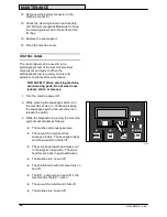
The sweeper assembly lowers and
raises.
D
The recovery tank auto-fill valve turns
on and off.
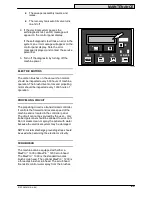
4. If the electrical system passes the
self-diagnostic test, an OK message will
appear on the control panel display.
If the self-diagnostic test finds an error in the
system, an error message will appear on the
control panel display. Note the error
message displayed, and contact the service
personnel.
5. Turn off the diagnostic by turning off the
machine power.
ELECTRIC MOTORS
The carbon brushes on the vacuum fan motors
should be inspected every 500 hours of machine
operation. The brush drive motors and propelling
motor should be inspected every 1000 hours of
operation.
PROPELLING CIRCUIT
The propelling circuit is a transistorized controller.
It controls the forward and reverse speed of the
machine and is located in the controller panel.
The circuit cannot be serviced by the user -- only
trained personnel should be allowed to work on it.
Do not steam clean or spray the panel with water
because the electrical system may be damaged.
NOTE: A static discharge grounding strap should
be used when servicing the electronic circuitry.
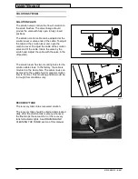
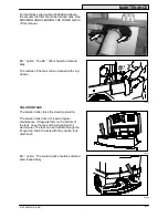
SCRUB HEAD
The machine can be equipped with either a
MaxPro
t
1000 or MaxPro
t
1200 scrub head.
The MaxPro
t
1000 is the standard two disk
brush scrub head. The optional MaxPro
t
1200 is
a three disk brush scrub head. The scrub head
floor skirts control water spray from the brushes.
10734

