MAINTENANCE
242E MM243 (5---92)
3-12
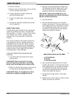
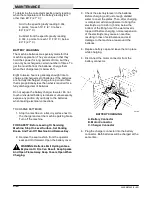
8. Stop the machine.
9. Raise the rear of the machine, remove the jack
stands, and lower the machine.
10. Fill the hydraulic fluid reservoir with new,
approved hydraulic fluid.
11. Check for system leaks. Correct any leaks
found.
12. Replace the hydraulic fluid filter after the first
hour of operation.
DIRECTIONAL PEDAL
The directional pedal controls the flow of hydraulic
fluid to the hydraulic drive motor. The pedal has
three positions --- “forward,” “neutral,” and “reverse.”
The “forward” and “reverse” positions sends
hydraulic fluid to the drive motor to propel the
machine.
The “neutral” position is the position in which the
propelling pump sends no hydraulic fluid to the
propelling motor. The machine should not creep
when the “neutral” position is correctly adjusted.
Adjust the directional pedal linkages whenever the
machine creeps or after replacing the hydraulic
propelling pump or pump linkages.
TO ADJUST DIRECTIONAL PEDAL NEUTRAL
POSITION
1. Turn off the machine and set the machine
parking brake.
FOR SAFETY: Before Leaving Or Servicing
Machine; Stop On Level Surface, Set Parking
Brake, And Turn Off Machine And Remove Key.
2. Block the machine tires and jack up the rear of
the machine at the designated locations.
FOR SAFETY: When Servicing Machine, Block
Machine Tires Before Jacking Machine Up.
3. Block up the machine with hack stands near
the designated locations. Make sure the rear
tire clears the floor by 2 in (50 mm) and all
obstacles within a 24 in (610 mm) radius.
FOR SAFETY: When Servicing Machine, Jack
Machine Up At Designated Locations Only. Block
Machine Up With Jack Stands.
4. Start the machine.
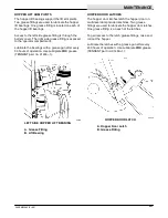
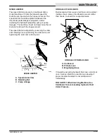
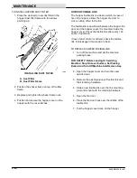
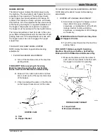
5. Move the directional pedal in the “forward”
position and release it. The rear wheel should
stop rotating as soon as the pedal is released.
Turn off the machine and loosen the screws
mounting the spring bracket to the machine
frame and to adjust as required.
A
B
C
05671
DIRECTIONAL PEDAL ADJUSTMENT
A. Spring Bracket
B. Spring
C. Directional Pedal
6. Move the directional pedal into the “reverse”
position and release it. The rear wheel should
stop rotating as soon as the pedal is released.
Turn off the machine and loosen the screws
mounting the spring bracket to the machine
frame and to adjust as required.
7. Tighten the mounting screws of the spring
bracket.
8. Raise the rear of the machine, remove the jack
stands, and lower the machine.
Summary of Contents for 242E
Page 1: ......
Page 10: ...SPECIFICATIONS 242E MM243 9 89 1 2 ...
Page 14: ...SPECIFICATIONS 242E MM243 9 89 1 6 ...
Page 16: ...OPERATION 242E MM243 5 92 2 2 ...
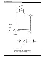
Page 62: ...MAINTENANCE 242E MM243 5 92 3 22 05805 ELECTRIC SCHEMATIC ...
Page 88: ...MAINTENANCE 242E MM243 5 92 3 48 ...
Page 90: ...APPENDIX 242E MM243 9 89 4 2 ...

