Artisan Technology Group - Quality Instrumentation ... Guaranteed | (888) 88-SOURCE | www.artisantg.com
Page 1: ...s underutilized and idle equipment along with credit for buybacks and trade ins Custom engineering so your equipment works exactly as you specify Critical and expedited services Leasing Rentals Demos In stock Ready to ship TAR certified secure asset solutions Expert team I Trust guarantee I 100 satisfaction All trademarks brand names and brands appearing herein are the property of their respective...
Page 2: ...al I I I i This manual contains procedures forgeneral and advanced operation assembly i interfacing interconnecting preventive maintenance and remote operation I I I parameters Artisan Technology Group Quality Instrumentation Guaranteed 888 88 SOURCE www artisantg com ...
Page 3: ...e Notice Patents have been granted and or patent applicationsare pending or are in process of preparation on all Temptronic Corporation developments The material in this manual is for informational purposes only and is subject to change without notice Temptronic Corporation assumes no responsibility for any errorsthat may appear in this manual Temptronic Corporation warrants this product as covere...
Page 4: ...of Figures and Lists of Tables see the beginning of each Section Front Matter I Sections 1 2 3 4 5 Safety Precautions ix General Data Section One Preparation for Use Section Two System Operation Section Three Remote Interfaces SectionFour Routine Maintenance SectionFive Back Matter Warranty Registration Cards PerformanceReport Reader comments Card Index Artisan Technology Group Quality Instrumenta...
Page 5: ...IC Gurr T1 j I Rev B 1 08 25 1999 1 Page 2 14 added Step 9 Locking Collar Page 2 15 inserted Drawing 13996B shows Locking Collar Page iv added Document Control table Artisan Technology Group Quality Instrumentation Guaranteed 888 88 SOURCE www artisantg com ...
Page 6: ...nts 2 1 2 2 Figures 2 2 2 3 Tables 2 2 2 4 Introduction 2 3 2 5 Receipt of Shipment 2 3 2 6 Placement Requirements 2 5 2 7 Unpacking Instructions 2 7 2 8 Overheat Safety SF1 and SF2 Sensors 2 9 2 9 Assembly Instructions 2 10 2 10 Thermal Cap Thermal Shroud Purge Air Attach 2 11 2 11 Wand Adjustable Stand Assembling 2 14 2 12 System 1njut1Output Panels 2 18 2 13 Main Power Connection 2 2 1 2 14 Air...
Page 7: ...Messages 3 46 3 17 Screen Tree Flow Diagram Thirteen Screens 3 48 4 Remote Interfaces 4 1 Contents 4 1 4 2 Figures 4 1 4 3 Tables 4 1 4 4 Introduction 4 3 4 5 Serial Interface 4 4 4 6 Parallel Bus Interface 4 5 4 7 Start Test ST End of Test EOT Stop on First Fail SFF 4 6 4 6 Host Interface Commands 4 9 5 Routine Maintenance 5 1 Contents 5 1 5 2 Figures 5 2 5 3 Tables 5 2 5 4 Introduction 5 3 5 5 I...
Page 8: ...arranty Registration Cards Performance Report Reader Comments Card Index RevA 06115 98 TP04100A Interface Applications vii Artisan Technology Group Quality Instrumentation Guaranteed 888 88 SOURCE www artisantg com ...
Page 9: ...e to record any notes Use the Reader Comments card at the back of thi submit any comments to Temptronic Corporation s manual to Use this space for system userloperator sketches Vlll Artisan Technology Group Quality Instrumentation Guaranteed 888 88 SOURCE www artisantg com ...
Page 10: ... earth ground in accordance with local electricalcodes WARNING 3 The locations of potentially dangerous voltages and other hazards such as hot surfaces are identified and labeled on the equipment Be careful to observe these warnings when installing operating maintaining or servicingthe equipment Observe all warnings given in this manual WARNING 4 Make sure to turn off the ac line power and the com...
Page 11: ...nd packaging procedures for ESD sensitive circuit boards Assume that all circuit boards are the ESD sensitivetype CAUTION 6 Unauthorized personnel should not remove from the equipment those panels that are provided for protection and or cooling and or require a tool to remove CAUTION 7 Use suitable Clean Dry Air CDA compressed air supply for the TP04100A system a to prevent premature fouling of th...
Page 12: ...ocCder au dkmontage ou 9 la maintenance corrective de 1 Cquipement AVERTISSEMENT 2 Pour Cviter tout risque d Clectrocution lYCquipement doit Stre mis 9 la terre 9 l aide d une prise de terre adCquateconformCment aux codes Clectriqueslocaux AVERTISSEMENT 3 Les endroits prCsentant des tensions potentiellement dangereuses et autres risques tels que les surfaces brQlantessont identifiks sur 1 Cquipeme...
Page 13: ...ans danger proche de la temp6rature ambiante AVERTISSEMENT 7 Lors de la connection des dCtecteurs a thermocouple au dispositif en cours d essai I DUT isoler Clectriquement les dCtecteurs afin de protkger les opCrateurs de tout contact avec des tensions 1 dangereuses d un site DUT i 1 1 ATTENTION 1 Certains matCriaux d emballage utilisCs pour I expCdition du TP04100A peuvent Ctre une i I source de ...
Page 14: ... air de sortie Une qualit6 inappropriCe d alimentation d air peut entrainer un endommagement Cventuel des composants internes de fonctionnement du systbme ATTENTION 8 Installer utiliser et entretenir correctement l ensemble de filtrelregulateur fourni avec le systhme TP04100A pour empCcher la pCnCtration de I humiditC et ou des huiles du compresseur dans les composants actifs du systeme Si ces pre...
Page 15: ...record any notes Use the Reader Comments card at the back of this manual to submit any comments to Temptronic Corporation Use this space for system userloperator sketches xiv 41A FRL doc Artisan Technology Group Quality Instrumentation Guaranteed 888 88 SOURCE www artisantg com ...
Page 16: ...inrichtung entsprechend den lokalen elektrischenVorschriften uber eine adaquateMasseleitung geerdet sein WARNUNG 3 Die Orte potentiell gef licherSpannungen und anderer Gefsihrdungen z B heil3er Oberflachen sind an der Einrichtung mit Etiketten gekennzeichnet Beim Installieren Bedienen Warten bzw bei Servicearbeiten an der Einrichtung sind diese Warnungen sorgfaltig zu befolgen Es sind alle in dies...
Page 17: ...statischer Aufladung sein Entpacken Sie nicht in der Nahe elektrostatischempfindlicher Bauteile VORSICHTZ Beachten Sie die in der Einrichtung selbst und in diesem Handbuch angegebenen Schutzmaljnahmen um die Einrichtung vor Beschadigungzu bewahren VORSICHT 3 Vor dem Anschlieljen des TP04100A an die Netzspannung ist zu uberpriifen ob die anliegende Wechselspannung und Frequenz den fur das TP04100A ...
Page 18: ...zu warten Dadurch wird das Eindringen von Feuchtigkeit undloder Kompressorol in die Baugruppen des Systems verhindert Im Vernachlassigungsfall kann das zu einer Beschadigung des Systemsf e n die nicht in die Garantieanspriicheeinbezogen ist VORSICHT 9 Die beiden ijberhitzung sicherheitssensoren SF1 und SF2 auf der riickwwigen Wand miissen bei normalem Betrieb mit Kappen verschlossen bleiben Wenn S...
Page 19: ...ge to record any notes Use the Reader Comments card at the back of this manual to submit any comments to Temptronic Corporation Use this space for system userloperatorsketches xviii Artisan Technology Group Quality Instrumentation Guaranteed 888 88 SOURCE www artisantg com ...
Page 20: ...ntro del equipo debe ser i6 1 permitido efectuarprocedimientos de desmontajeo mantenimientocorrectivo Z ADVERTENCIA 2 Para evitar riesgos de choques el ricos el equipo deberii estar puesto a tierra con una conexi6n adecuada a tierra fisica de acuerdo con 10s c6digoselCctricos locales ii I ADVERTENCIA 3 Los lugares donde existen tensiones peligrosas y otros riesgos tales como superficies I caliente...
Page 21: ... de la arnbiente y sin peligro ADVERTENCIA 7 Cuando conecte sensores termopares a1 dispositivo en prueba DEP aisle eldctricamente 10s sensores para proteger a 10s operadores contra contactos con cualquier tensi6n peligrosa en el sitio del DEP PRECAUCION 1 Algunos de 10s materiales de empaque para el embarque del TP04100A podrian ser una fuente de descarga de electricidad estatica No desempaque la ...
Page 22: ...de aire de salida La calidad inferior del suministro de aire podria causar daiios a 10s componentes operativos internos del sistema PRECAUCION 8 Instale use y mantenga en forma apropiada el conjunto de filtro regulador suministrado con el SistemaTP04100A De esta manera se evitara la entrada de humedad y o aceite del compresor a 10s componentes operativos del sistema Si no se verifica este disposit...
Page 23: ...e to record any notes Use the Reader Comments card at the back of this manual to submit any comments to Temptronic Corporation Use this space for system user operator sketches xxii Artisan Technology Group Quality Instrumentation Guaranteed 888 88 SOURCE www artisantg com ...
Page 24: ... 2 Remote Operation ThermoCommSoJtware Optional 1 5 1 6REGISTRATION CARDS PERFORMANCE REPORT WARRANTY 1 7 1 6 1 Usedowner Registration Cards 1 7 1 6 2 Performance Report Forms 1 7 1 6 3 Warranty 1 7 1 7 SPECIFICATIONS 1 7 1 8SYSTEM MODEL NUMBER DESIGNATION j 1 9 1 2 Figures FIGURE 1 1 MODEL TP04100ATHERMOSTREAM SYSTEM 1 3 1 3 Tables TABLE 1 1 SYSTEM MODEL NUMBER DESIGNATION 1 9 Page 1 1 Artisan Te...
Page 25: ...is page to record any notes Use the Reader Comments card at the back of this manual to submit any comments to TemptronicCorporation Use this space for system userloperator sketches Page 1 2 Artisan Technology Group Quality Instrumentation Guaranteed 888 88 SOURCE www artisantg com ...
Page 26: ...splay screen shows the active temperature the temperature setpoints soak times ramp rates up and down how many cycles are being performed and the Device Under Test DUT sensor sel ection Additional program screens facilitate programming of Test Setups system configuration define the limits of operation and calibrate the system In addition complete system operation status and any error messages are ...
Page 27: ...s page to record any notes Use the Reader Comments card at the back of this manual to submit any comments to Temptronic Corporation Use this space for system usedoperator sketches Page 1 4 Artisan Technology Group Quality Instrumentation Guaranteed 888 88 SOURCE www artisantg com ...
Page 28: ...ee 110 s for three different communication interfaces Serial RS232C Parallel Bus GPIB IEEE 488 2 and STEOTISFF Interface A summary of the three 110 s and also of ThermoComm Software mentioned below is given in Section 2 Remote Control Communications See Section 4 Remote Interfaces for detailed instructions and command sets ThermoCommSoftware optional is a Windows 3 1195198lNTapplicationwhich enabl...
Page 29: ...s page to record any notes Use the Reader Comments card at the back of this manual to submit any comments to Temptronic Corporation Use this space for system user operator sketches Page 1 6 Artisan Technology Group Quality Instrumentation Guaranteed 888 88 SOURCE www artisantg com ...
Page 30: ...rformance Report is provided at the back of this manual Use this report to submit any desired enhancements or functional discrepancies in the system For prompt response you may contact the Temptronic Service Department directly whenever a problem occurs See the Introduction to Section 5 Routine Maintenance for information on how to contact Service Also a Reader Comment card is included at the back...
Page 31: ...s page to record any notes Use the Reader Comments card at the back of this manual to submit any comments to Temptronic Corporation Use this space for system userloperator sketches Page 1 8 Artisan Technology Group Quality Instrumentation Guaranteed 888 88 SOURCE www artisantg com ...
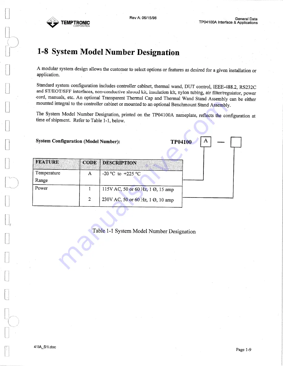
Page 32: ...or power cord manuals etc An optional Transparent Thermal Cap and Thermal Wand Stand Assembly can be either mounted integral to the controller cabinet or mounted to an optional Benchmount Stand Assembly The System Model Number Designation printed on the TP04100A nameplate reflects the configuration at time of shipment Refer to Table 1 1 below System Configuration Model Number Temperature A 20 O C ...
Page 33: ...d any notes Us Rev A 06 15 98 e the Reader Comments card at the back of this manual t submit any comments to Temptronic Corporation Use this space for system usedoperator sketches Page 1 10 Artisan Technology Group Quality Instrumentation Guaranteed 888 88 SOURCE www artisantg com ...
Page 34: ... 13MAINPOWER CONNECTION 2 21 2 14AIRCONNECTIONS 2 21 2 15 STATIC MOISTURE TEMPERATURE EXTREME PROTECTION 2 23 2 15 1 Overview 2 23 2 15 2 ElectrostaticDischarge ESD Protection 2 23 2 15 3 Moisture Protection 2 24 2 15 3 1 Overview 2 24 2 15 3 2 Seal Out Moisture Inflows DUT Socket 2 24 2 15 3 3Air Purging the Tester Platform 2 2 4 2 15 4 TemperatureExtreme Protection 2 25 2 15 4 1 Insulation Minim...
Page 35: ...ACKING CARTON FOR SHIPMENT 2 3 FIGURE 2 2 PLACEMENT CLEARANCES FOR TP04I O O A 2 5 FIGURE 2 3 UNPACKING TP04100A BASECONTROLLER ARM CLAMPS OPTIONAL THERMAL CAP OPTIONAL AIRLINE U CLAMP POWER CORD 2 8 FIGURE 2 4 THERMAL CAPATTACHMENT OPTIONAL TRANSPARENT CAPSHOWN 2 12 FIGURE 2 5 THERMAL WAND AIRPURGE OUTLETFITTING 2 13 FIGURE 2 6 THERMAL WAND STAND ASSEMBLE SUPPORT COLUMN 2 15 FIGURE 2 7 THERMAL WA...
Page 36: ...r location by two people Overall shipping size of the packaged system is 20 inches 50 8 cm deep by 33 5 inches 85 1 cm wide by 29 5 inches 74 9 cm high Overall shipping weight is approximately 78 pounds 35 5 kilograms All items purchased are included inside the packing carton When received the carton should be examined for any signs of mishandling or damage during shipment Figure 2 1 TP04100A in P...
Page 37: ...RPORATION Use this page to record any notes Use the Reader Comments card at the back of this manual to submit any comments to Temptronic Corporation Use this space for system userloperator sketches Page 2 4 Artisan Technology Group Quality Instrumentation Guaranteed 888 88 SOURCE www artisantg com ...
Page 38: ...ng of the TP04100A and for affording a minimum workspace the system should be located with minimum clearances side 1inch rear 6 inches see Figure 2 2 N o h Minimumclearances requimd from sides and mar of system to milandlor benchfor properoperation CLEARANCEFOR 20 FULLARM MOTION 30 6 t775mml RADIUS Thermal Wand OUTPUT WORKING CENTERLINE 2 V t660nunlRADIUS Facilities supplyhosefrom rear of Syrtom t...
Page 39: ...ment Servicing for a description of the System air FilterIRegulator See Section 1 Specifications for required compressed air supply pressure The supply flow must be capable of the specified minimum litreslsecond L S Standard Cubic FeetMinute SCFM A supply pressure below the minimum results in a reduced performance For sustained low temperature operation and testing with the TP041OOA clean dry air ...
Page 40: ...nde Warnungs oder Vorsichtsnummer im Abschnitt iiber Vorsichtsmal3regeln am Anfang dieses Handbuchs PRECAUCION 1 Vea el n6mero de la Advertencia o Precaucih en la secci6n de Precauciones de Seguridad a1comienzo de este manual 2 Cut and remove the band seals holding the packing carton on its skid if any Remove carton strappingand lift off the carton cover and the carton shell See Figure 2 1 3 Visua...
Page 41: ...nal Thermal Cap optional Air Line U Clamp Power Cord NOT PICTURED Shroud Kit Foam Rubber Insulation Kit seeFigure 2 1 1 on page 2 27 Thermocouple Disc Kit see Section 2 17 2 on page 2 3I and Air Filter Regulator see Section 5 Air Filter Element Servicing Page 2 8 Artisan Technology Group Quality Instrumentation Guaranteed 888 88 SOURCE www artisantg com ...
Page 42: ...r panel see Figure 2 8 are designedas independent redundant safety protection against system thermal runaway Leave both SF1 and SF2 plugged into the rear panel at all times SF1 and SF2 are for system use only If SF2 secured with a protective strap is not plugged into the rear panel input when the system is powered up then an internalfuse will blow disabling heater function Qualified service person...
Page 43: ...n page 2 11 3 Connect electrical power see Section 2 13 on page 2 21 4 Connect compressedair see Section 2 14 on page 2 21 5 Protect test site static moisture temperature extremes custom test enclosures see Section 2 15 on page 2 23 and Section2 16 on page 2 28 6 Interface and attach thermocouples optional see Section 2 17 on page 2 30 7 Interfaceto Remote Control Communications optional see Secti...
Page 44: ...ed one for the type of DUT being tested replacement shroudsare available from Temptronic Attach the purge air hose to the air purge output fitting located above the wand handle grips see Figure 2 5 Then insert the other end of the purge air hose which is connected to a circular tube perforated with air vents into the bottom circumference of the thermal cap sothat the purge air vents upward into th...
Page 45: ...A 06115 98 Attach Thermal Cap as given above and illustrated below Page 2 12 TEMPTRONIC CORPORATION Figure 2 4 Thermal Cap Attachment Optional TransparentCap Shown Artisan Technology Group Quality Instrumentation Guaranteed 888 88 SOURCE www artisantg com ...
Page 46: ...TION Rev A 06115 98 Preparationfor Use TP04100A Interface Applications Figure 2 5 Thermal Wand Air Purge Outlet Fitting Page 2 13 Artisan Technology Group Quality Instrumentation Guaranteed 888 88 SOURCE www artisantg com ...
Page 47: ...ening until the Dowel Pin is seated in its mating hole in the center of the bottom of the circular opening in the controllercabinet Place the controller cabinet on its side so that the mounting holes located on the base of the controller cabinet are exposed Rotate the Support Column so that its three threaded mounting holes are concentric with the controller cabinet mounting clearance holes On eac...
Page 48: ...ons MOUNTING HOLES AIR LINE U CLAMP A 8 SUPPORT CDLUMN FLAT WASHER LOCK WASHER SOCKET HEAD CAP SCREW 13996B Figure 2 6 Thermal Wand Stand Assemble Support Column 41IA RvB S2a doc Page 2 15 Artisan Technology Group Quality Instrumentation Guaranteed 888 88 SOURCE www artisantg com ...
Page 49: ...Figure 2 7 Place the Vertical Column Clamp over the vertical Support Column and slide it down the Support Column and tighten the Vertical ColumnLock The inside circumference of the Vertical Column Clamp is circular and does not have Detent Inserts within it Remove the two caps from the ends of the Horizontal Arm and slide one end of the Horizontal Arm into the Vertical Column Clamp tightenthe Hori...
Page 50: ... of the ThermoWand during extended low temperaturetesting As a heat shield this assembly protects the user s hand from being exposed to high temperature air flow This exposure is only a risk when the ThermoWand is being used as a hand held device AND a Thermal Shroud is being utilized without a Thermal Cap In applications where a Thermal Cap is being used and no low temperature testing is being co...
Page 51: ... A TEMPTRONlC TII CORPORATION 2 12 System Input Output Panels FigurC2 9 System Input Output Rear Panel 4 t c Page 2 18 Figure 2 10 Thermocouple Sockets Dut T Dut K Front Panel Artisan Technology Group Quality Instrumentation Guaranteed 888 88 SOURCE www artisantg com ...
Page 52: ... Port socket DUT T on front panel I HAO I Heater Air Out I Use To Interface Type T Thermocouple Sensor for DUT I MA TC IMain Air Thermocouple useto Calibrate I HP1 IEEE 488 Heater Power 1 IEEE 488 2 Parallel Communications I PWR 1 IEC 320 ac Power Input I I I RS232C I RS232C Serial Communications I PG 0 I SF1 TC ISafety1 Thermocouple system use only I Purge Air Output I SF2 TC Safety2Thermocouple ...
Page 53: ...this page to record any notes Use the Reader Comments card at the back of this manual to submit any comments to Temptronic Corporation Use this spacefor system user operator sketches Page 2 20 Artisan Technology Group Quality Instrumentation Guaranteed 888 88 SOURCE www artisantg com ...
Page 54: ...2 4 meter 8 feet long line cord and IEC 320 male power connector socket 2 14 Air Connections See Figure 2 8 System Input Output Rear Panel for compressed air input fitting SP1 Supply Pressure I located on the Controller cabinet rear panel For Compressed Air Standards required for system operation see Section 2 6 3 The TP04100A is supplied with a 3 7 meter 12 feet iong 318 inch inside diameter nylo...
Page 55: ...ller air input SPI Use appropriate hose clamps to secure each hose end between the compressedair source and the FilteriRegulator NOTE Refer to the Specifications data sheet included in Section 1 for the compressed air requirements Turn on the compressed air supply to the FilterRegulator Set the regulator on the Filter Regulator for a reading of 80 psi on its pressure gauge Page 2 22 Artisan Techno...
Page 56: ...or separated Such an electrostatic discharge ESD can also be generated by the discharge of compressed air or other inert gases over a surface regardless of the airjet velocity but increasingly at higher sustained airjet velocities The airflows through Temptronic ThermoStream pneumatic systems have been extensively researched and designed to provide ionically neutral air free of static charge at th...
Page 57: ... 2 11 Typical Insulationfor DUT 2 15 3 3 Air Purging the TesterPlatform Condensation frosting and ice can appear on the tester platform test board and its test cables socket lead wires and related interconnections during low temperature testing unless the platform area is properly purged with system supplied dry air as given below For instance if the tester platform is exposed to ambient room air ...
Page 58: ...al conduction paths to the DUT test socket test leads and other fixturing features To minimize conductivity fit and seal insulation materials as given below 2 15 4 2 Insulation Kits Fitting and Sealing Each TP04100A is supplied with a standard insulation kit P N ZAK101890 which contains a sheet A inch thick of 12 inchsquare silicone foam material The silicone material combines the property of low ...
Page 59: ...MAlRSmEAM T O Dm NOTE TEMPERANRETWWSmONTIMESARE DEPENMMONhnASS SPECIFICH E A TCHARACTERISTICSANDT H EMERMAL COUPUNGANDTHERMALCONDUCTIONPAW T OMED U T T E S TSOCW T E S TLEADSS D OTHERFDrmRlNGFEATURES IMERFACESEAL KEEPSOUTMOISTURE FROMD U TAREA THERMALSHROUD CONCENTRATES AIRAROUND D U T WISENSOR CONNECT07 7 ToTHERMOSIREAM FRONTPANEL DUTSENSOR L T E D mP PAnt mtm WANDT R A V E L FORINSERTINGAND ExmA...
Page 60: ...RPORATIOt Rev A 06115 98 Preparationfor Use TP04100A Interface Applications Figure 2 12 Typical Insulation for DUT Page 2 27 Artisan Technology Group Quality Instrumentation Guaranteed 888 88 SOURCE www artisantg com ...
Page 61: ...ature control over and beyond the MilSpec temperaturerange These enclosures apply to testing characterization and failure analysis of printed circuit boards PCBs component arrays hybrids and small electronic and electromechanical subassemblies including multichip modules MCMs radio frequency RF microwave or digital high speed high power devices and provide ESD free and frost free test environments...
Page 62: ...indow on two sides to allow two operators simultaneous access or one operator access to both sides without having to remove rotate and reinsert the Device Under Test CTTEs are available for both edge connector and in circuit bed of nails PCB test applications and can be configured to meet a variety of test requirements A ThermoFixture holds the module or device in a custom socket at temperature in...
Page 63: ...erature measurement sensor that consists of two dissimilar metals joined together at one end a junction which produces a small thermoelectric voltage when the junction is heated The change in thermoelectric voltage is interpreted by thermocouple thermometers as a change in temperature This Section explains a How to interface install a thermocouple to the TP04100A and the related tester fixture soc...
Page 64: ...external thermocouple Follow these sensor interfacingguidelines All materials used in fixturing should be capable of withstanding the total system specified temperature range as listed in the System Specification see Section 1 Specifications The DUT sensor must be located within the test fixture be in contact with the DUT and be properly connected to the appropriateInput port socket on the Systemf...
Page 65: ... Do not ground the sensor if the DUT case is grounded then isolate the sensor by using a material which is electrically nonconductive but is an excellent thermal conductor It is preferable that the thermocouplejunction and approximately 20 30x the thermocouple wire diameter be in contact with the center of the DUT to minimize heatsinking see Figure 2 13 Alternative Thermocouple Attachment Mount th...
Page 66: ...eGuidelines 1 Install the sensor element on the DUT test socket to contactthe DUT when inserted in the socket See Drawing 4714 at end of Section2 and follow the conceptstherein to modify the test socket 2 Plug the connector on the other end of the thermocouple wiring into the DUT T port on the System Front Panel see Figure 2 9 If the interface steps above are not consistent with your test specimen...
Page 67: ...T test socketto contactthe DUT when the DUT is inserted in the socket 2 See the Drawings referenced for T type factory supplied thermocouples above and follow the concepts therein to modify the test socket 3 Plug the connector on the other end of the thermocouple wiring into the DUT K port on the System Front Panel see Figure 2 9 If the interface steps above are not consistent with your test speci...
Page 68: ...013 mm will conduct more heat between the test specimen DUT and the ambient resulting in less accuratetemperature measurements Make the thermocouplejunction as small as possible Do not ground the sensor if the DUT case is grounded then isolate the sensor by using a material which is electricallynonconductive but is an excellent thermal conductor It is preferablethat the thermocouplejunction and ap...
Page 69: ...ON THERMOCOUPLE JUNCTlON P O I N A k SOLDERED UMSFACIDRY TESTSPECIMEN lHEIWlOCaRLE B SOLDERED BEER THINCOATOF THERMGREASE 1 UNSOLDERED RllNCOPPERPWE SIICK ON THERMOCOUPLE 2 WDERED A D H E W BACKED Figure 2 14 Alternative Thermocouple Attachment Page 2 36 Artisan Technology Group Quality Instrumentation Guaranteed 888 88 SOURCE www artisantg com ...
Page 70: ...satisfactory Junction Does not Contact Solder Sensor junction is out of direct contact with DUT wires firstjoin at point A temperature is being measured at point A B Better Junction Contacts DUT but Thermocouple Wire may conduct heat to or from ambient C Best Thermocouple Wire Contacts DUT Surface approximately20 30 Times Diameter of Sensor Wire Unsoldered techniques 1 Thin Copper Plate Used with ...
Page 71: ... information and special programming instructions It is suggested the end user firstverify proper system operationbefore attempting to use programs developed by the end user 2 18 3 ST EOT SFF Interface An ST EOT SFF interface between the TP04100A and a tester is standard The interface cable from the tester plugs into the ST EOT SFF connector on the TP04100A rear panel Interface connections signals...
Page 72: ...er then LabView by National Instrumentsis required and enables function on any Windows platform 3 1 95 NT LabView is not required if instding and running only the built application but the built application without LabView installed will function only on Windows 95 and NT For details contact TemptronicCorporation Page 2 39 Artisan Technology Group Quality Instrumentation Guaranteed 888 88 SOURCE w...
Page 73: ...EEE 488 2 or RS232C operation see Section 4 Remote Interfaces in this manual 2 19 1 Main Power Switch MAIN POWER SWITCH POWER INDICATOR LAMP 3 sal Figure 2 15 Main Power Switch Page 2 40 41IA S2F doc Figure 2 13 shows the Main Power Switch located on the right hand side of the controller s front panel This switch also serves as the primary ac power circuit breaker CB1 for the system An IEC 320 con...
Page 74: ...creen then press the System button to select the ConJigureSystem Screen At the Configure System Screen select the parameters to give the desired system operation for details see Section3 Configure System set Auto Start MANUAL OPERATION to On if you wish to start up in Manual Operation Mode leave Off to start up in Program Operation Mode After making the proper selections press Done to return to To...
Page 75: ...or approval is required before shipping the system to a Temptronic Sales Service Office or to the factory IT IS RECOMMENDED THAT A TAG BE ATTACHED TO THE SYSTEM GIVING THE OWNER S NAME ADDRESS TELEPHONE NUMBER SYSTEM MODEL AND SERIAL NUMBERS AND THE REASON FOR RETURN INCLUDING ANY RETURN MATERIAL AUTHORIZATION RMA NUMBERS Page 2 42 Artisan Technology Group Quality Instrumentation Guaranteed 888 88...
Page 76: ...9 3 7 USERINTERFACE 3 13 3 8 TO SHUTDOWN THE TP04100A SYSTEM 3 17 3 9 SYSTEM STARTUP SCREEN 3 19 3 10 TOPMENU SCREEN PROGRAM OPERATION MODE 3 20 3 11CONDUCTING TESTS 3 23 3 12 SETTING UPTESTS 3 27 3 13 MAINAIRMODE TESTSETUP 3 40 3 14DUT MODE TESTSETUP 3 42 3 15 CONFIGURE SYSTEM 3 44 3 16ERROR MESSAGES 3 46 3 17 SCREEN TREEFLOW DIAGRAM THIRTEEN SCREENS 3 48 Page 3 1 Artisan Technology Group Quality...
Page 77: ...this page to record any notes Use the Reader Comments card at the back of this manual to submit any comments to Temptronic Corporation Use this space for system usedoperator sketches Page 3 2 Artisan Technology Group Quality Instrumentation Guaranteed 888 88 SOURCE www artisantg com ...
Page 78: ...tons 3 14 3 7 4 T and K DUT Sensor Inputs 3 14 3 7 5 Flow Adjustment Valve 3 14 3 7 6 Rotary Encoder 3 15 3 8 TO SHUTDOWN THE TP04100A SYSTEM 3 17 3 9 SYSTEM STARTUP SCREEN 3 19 3 10 TOPMENUSCREEN PROGRAM OPERATION MODE 3 20 3 10 1 TopMenu ScreenSelections 3 21 3 11 CONDUCT NG TESTS 3 23 3 11 1 Overview 3 23 3 11 2 Program OperationScreen Air Mode 3 24 3 11 3 Program OperationScreen DUTMode 3 26 3...
Page 79: ...lds 3 35 3 12 5 Default 0 Setup ThreeData Setsper Setup 3 36 3 12 5 1 Default 0 Zero Test Setup 3 36 3 12 5 2 Data Sets Per Setup Manual Program Defined Parameters 3 37 3 12 6 CopySetup Screen 3 38 3 13 MAINAIRMODETESTSETUP 3 40 3 13 I Overview 3 40 3 13 2 DeJne Parameters Air Mode Test Setup 3 41 3 14 DUT MODETESTSETUP 3 42 3 14 1 Overview 3 42 3 14 2 DeJne Parameters DUTMode TestSetup 3 43 3 15 ...
Page 80: ...3 24 FIGURE 3 8 PROGRAM OPERATION AIRMODE CYCLING 3 25 FIGURE 3 9 PROGRAM OPERATION SCREEN DUT MODE 3 26 FIGURE 3 10 SETUP OPTIONS SCREEN 3 28 FIGURE 3 11DEFINE PARAMETERS SCREEN 3 29 FIGURE 3 12 PROGRAM TESTSETUP SCREEN 3 33 FIGURE 3 13 COPY TEST SETUP SCREEN 3 38 FIGURE 3 14 DEFINE PARAMETERS SCREEN AIRMODE TESTSETUP 3 41 FIGURE 3 15DEFINE PARAMETERS SCREEN DUTMODE TYPEK TESTSETUP 3 43 FIGURE 3 ...
Page 81: ...his page to record any notes Use the Reader Comments card at the back of this manual to submit any comments to Temptronic Corporation Use this space for system userloperator sketches Page 3 6 Artisan Technology Group Quality Instrumentation Guaranteed 888 88 SOURCE www artisantg com ...
Page 82: ... summaries in this sub section A ConductingTests see Overview Section3 1I I on page 3 23 B Setting Up Tests see Overview Section 3 12 1 on page 3 27 3 5 2 Conducting Tests In Program Operation Mode the operator can conduct tests in either of the temperature control modes mentioned above Main Air mode or DUT mode A test will run however only if its related test setup parameters have been properly p...
Page 83: ...test For a detailed summary see Section 3 12 1 I I 3 5 4 Self Tune DUT Modes 1 1 Self tuning allows the system to learn and adapt itself successively to match DUT mass for the best compromise between minimal overshoot and fastest temperature transition time DUT mode self tuning is 4 automatic so long as it is selected on the Define Parameters Screen see Figure 3 1 1 and optimizes operation I by me...
Page 84: ... that SF1 and SF2 overheat Safety sensors are connected on the rear panel If SF2 is disconnected and the system is powered On then an internal fuse will blow and have to be replaced by qualified service personnel Actuate the Main Power Switch located on the front panel of the controllercabinet upward to the 1 ON up position to start operation of the TP04100A Power onloff Indicator Lamp will light ...
Page 85: ...rm of the stand When this lock is loosened the horizontal a r m can be turned up to 170 degrees in either horizontal direction from the front of the system and be repositioned up or down along the vertical axis of the column HORIZONTAL ARM LOCK A on the same assembly as but opposite to the Vertical Column Lock can be tightened to clamp any rotational and linear movement of the horizontal arm from ...
Page 86: ... Operation TEMPTRONIC TP04100A Interface Applications v ZOFD iaATICI I 1 Figure 3 2 Thermal Head Manipulator Positioning Page 3 11 Artisan Technology Group Quality Instrumentation Guaranteed 888 88 SOURCE www artisantg com ...
Page 87: ...System Operation TP04100A Interface Applications RevA 06115 98 Page 3 12 Figure 3 3 Thermal Wand Handle Grips Artisan Technology Group Quality Instrumentation Guaranteed 888 88 SOURCE www artisantg com ...
Page 88: ...ted at the center of the controller front panel is an amber monochrome electroluminescentdisplay approximately5 5 inch size in diagonal measurement This graphical user interface provides a highly visible readout of operational information It allowstest engineers production operators and non technical individuals optimum ease of use with minimum learning time The operational screens display the fol...
Page 89: ... external type T and type K thermocouple sensors to monitor the actual temperature of the device component being thermally tested The application operation and use of DUT sensors is discussed in Section 2 The verification and calibrationof DUT sensors is discussed in Section 5 3 7 5 Flow Adjustment Valve The Flow Adjustment valve is located to the left of the Graphical Display Screen This valve is...
Page 90: ...reasethe parameter value To Terminate Press ESC Escape Program Button to exit the present program screen No Encoder knob press is required to terminate Press Encoder knob once to accept the parameter change and return to Step Mode or press ESC Escape Program Button to cancel the parameter change and return to Step Mode Table 3 1 Rotary Encoder Operation Step Mode and Change Mode As given in Table ...
Page 91: ... Notes Use this page to record any notes Use the Reader Comments card at the back of this manual to submit any comments to Temptronic Corporation I Use this space for system user operator sketches Page 3 18 Artisan Technology Group Quality Instrumentation Guaranteed 888 88 SOURCE www artisantg com ...
Page 92: ...peration when the System Startup Screen is displayed Press any Program Button to continueto the TopMenu Screen If Auto start in MANUAL OPERATION is set to ON in the ConJigureSystem Screen see Figure 3 16 then the system will automatically start in Manual mode and display the Manual Operation Screen see the TP04100A Operator s Manual For a flow diagram of the thirteen TP04100A screens seethe Screen...
Page 93: ...go to Manual Operation mode The Manual Operation mode see the TP04100A Operator s Manual has a maximum selection of 10unique test setups and facilitates production run testing Each Manual Operation test setup includes a hot setpoint a cold setpoint and an ambient setpoint Manual cycling is specifically for a three setpointprogression The Program Operation mode see Section 3 11 2 accesses a maximum...
Page 94: ...creen see Figure 3 16 on page 3 44 FLOW This selection allows the operator to toggle the hot air flow of the Thermal Wand ON and OFF without temperature control The first press of the FLOW program button turns the hot air flow ON the second press turns it OFF This allows the operator to verify and or adjust system hot air flow for hot setpoint temperatures of 33 1 C through 225 C Use the Flow Adju...
Page 95: ...his page to record any notes Use the Reader Comments card at the back of this manual to submit any comments to Temptronic Corporation Use this space for system userloperator sketches Page 3 22 Artisan Technology Group Quality Instrumentation Guaranteed 888 88 SOURCE www artisantg com ...
Page 96: ... Section 3 12 Setting Up Tests The next paragraphs describethe Program Operation mode for testing by 1 Cycling from two up to 10setpoints by using the Cycle function on the Program Operation Screen 2 Ramping and soakingfor the cycling sequences as defined using the Program TestSetup Screen To test from a manuallyselected setpoint using the Manual OperationScreen see the TP04100A Operator s Manual ...
Page 97: ... summarized as follows To execute a function press the corresponding Program Button ESC This selection returns the operator to the previous program screen unless the system is running to a setpoint in which instance the system stops running to the setpoint ESC can also be used to exit the Change Mode and cancel any changes made to the selected parameter value ROW This selection chooses an entire r...
Page 98: ...elect Define to display Define Parameters Screen and check the Maximum test time sec setting This sets how long in seconds the system will remain At Temperature after the soak time has elapsed before advancing to the next cycle step Use Select to select ccMaximumtest time sec and use the Rotary Encoder to adjust the setting To proceed to next temperature during cycling without delay set to 0 zero ...
Page 99: ...ure 3 1 1 on page 3 29 and DUT Mode Test Setup Section3 14 on page 3 42 The Program OperationScreen DUT Mode allows the operator to perform all the same functions as given on the Program OperationsScreen Air Mode For a detailed explanation of each menu command Esc Row Step Cycle and Setup see Section 3 11 2 In the figure above notice that the main temperaturewindow is labeled DUT Note if the syste...
Page 100: ...ge 3 42 Each test setup file contains the system setup parameters and temperature setpoints to allow a DUT to be tested over a ramplcycle sequence of up to 10temperature setpoints Different test setup files are programmed through the Program TestSetup Screen see Figure 3 12 By using the factory defaults or by accessing a previously saved test setup see Copy Setups Screen Figure 3 13 a new setup ca...
Page 101: ...her Test Setup parameters Select Copy to copy Test Setups or CAL to calibratethe system The function selections at the bottom of the display screen in Figure 3 10 are summarizedas follows ESC This selectionreturns the operator to the previous program screen I MANUAL This selection takes the operator to the Manual Test Setup Screen see TP04100AA Operator s Manual I PROGRAM This selectiontakes the o...
Page 102: ...3 12 3 1 Define Parameters Screen Selections ESC This selection returns the operator to the previous program screen or is used to exit the Change Mode and cancel any changes made to the selectedparametervalue SELECT This selection steps through and frames each Test Setup parameter sequentially from top to bottom The first press selects DUT control The second press moves down to select DUT sensor a...
Page 103: ...ctsthe use of a DUT type K thermocouple sensor T Selectsthe use of a DUT type T thermocouple sensor 3 12 3 3 DUT control Of5 On SetupParameter Allows the operator to set system temperature control to be from one of two sources from the main air thermocouple sensor or from an external DUT sensor Off Selectsthe main air thermocouple sensor for system temperature control Main Air mode On Selects an e...
Page 104: ...hen operating the system in DUT control mode Accepted values are any between 10 C and 225 C in 1 C increments When the system is shipped this value is set to 225 C to ensure minimum transition times between temperatures The software applies this value symmetrically as the maximum allowabletemperature differential between the air temperature and DUT temperature as read by the system It will apply e...
Page 105: ...by the system This is primarily useful when using the ramplcyclemode of system operation but it has other valid uses described below Because the system is capable of being coupled with automatic test equipment utilizing standard start test ST and end of test EOT signals this feature can work in two ways First it allows simple operation utilizing only the start test signal from the system to the ho...
Page 106: ...tSetupScreen The Program TestSetup Screen consists of five program button functions and five windows Functions ESC SELECT DEFINE ADD DONE press button below function to execute Ramp UPIDOWN Fields Temperature Band WINDOW Number of CYCLES Test Setups 0 9 Setpoints per Test Setup Add C Secs Soak Time Seconds Use the Rotary Encoder see Table 3 1 to navigate the five windows except Test Setups 0 9 whi...
Page 107: ...ent highlighted Test Setup program places it into the 0 Test Setup program location see Section 3 12 5 1 on page 3 36 then returns the operator to the Program Operation Screen see Figure 3 9 The program parameter values used on the Program OperationScreen are always values stored in the 0 Test Setupprogram Each of the five windows on the Program Test Setup Screen are summarized as follows 3 12 4 2...
Page 108: ... field after which the system is At Temperature and sends a Start Test signal to the tester station Use the Rotary Encoder to select and set the seconds value See Maximum test time seconds in Section 3 12 3 9 on page 3 32 to prevent cycling from becoming hung stalled if no End of Test signal is received from the tester station Ramp UPADOWN Fields Allows the operator to program a Ramp rate value in...
Page 109: ...rogram Saved values are retained in Test Setup 0 even if the system is turned off Similarly any changes made to any active setpoint temperature or system parameter value are stored in this default Test Setup 0 program When an active Setup setpoint is being changed the system maintains temperature control at the old setpoint value until the new setpoint value is entered by pressing in on the Rotary...
Page 110: ...herefore each Test Setup 0 9 contains Manual mode data Program mode data and a common set of Defined Parameters data DUT mode parameters Air to DUT max OC Minimum maximum air temperatures Maximum test times At Temperature see the DeJine Parameters Screen Changing a Test Setup only changes that active Test Setup mode it does not change Setups in other modes and does not change the common Defined Pa...
Page 111: ...nation Setup Default 0 Test Setup from which all tests are conducted and the three Data Sets which comprise Setups 0 to 9 are explained in detail on page 3 36 and page 3 37 The function selections at the bottom of the display screen in Figure 3 13 are summarized as follows ESC This selection returns the operator to the previous program screen or if COPY has not first been pressed is used to exit t...
Page 112: ...rite erase the destination Setup with the source Setup 1 i When Copy is pressed Done appears momentarily on the screen To retain the original source Setups i r and to exit without copying press ESC Page 3 39 Artisan Technology Group Quality Instrumentation Guaranteed 888 88 SOURCE www artisantg com ...
Page 113: ... Following is a setup for Main Air mode See the DeJne Parameters Screen for detailed explanations of each parameter Once parameters are defined then use the Program Operation Screen to conduct the tests first setup on the Program TestSetup Screen For a flow diagram of the thirteen TP04100A screens see the Screen Tree in Section3 17 on page3 48 Page 3 40 Artisan Technology Group Quality Instrumenta...
Page 114: ... Constant 20 500 Air to DUT max C Air temperature max C Air temperature min OC Figure 3 14 Define Parameters Screen Air Mode Test Setup 100 20 to 5001 225 I0 to 2251 225 25 to 2251 20 25to 991 I Page3 41 Maximum test time seconds 5 0 to 9 9991 Table 3 3 Define Parameters AirMode Test Setup Artisan Technology Group Quality Instrumentation Guaranteed 888 88 SOURCE www artisantg com ...
Page 115: ...he fastest possible temperature transition times while minimizing the amount of undershoot and overshoot see DUT self Tuning control Section 3 12 3 4 on page 3 30 Following is a setup for DUT mode See the Define Parameters Screen for detailed explanations of each parameter Once parameters are defined then use the Program Operation Screen to conduct the tests first setup on the Program TestSetups S...
Page 116: ...ntrol DUT Thermal Constant 20 500 I Air temperature max C 1 225 25to 2251 I ON Off On 100 20 to 5001 I Air temperature min OC 1 20 25to 991 I Maximum test time seconds 1 60 0to 9 9991 I I I I Table 3 4 Define Parameters P U T Mode Test Setup Figure 3 15 Define Parameters Screen DUT Mode Type K Test Setup Page 3 43 Artisan Technology Group Quality Instrumentation Guaranteed 888 88 SOURCE www artisa...
Page 117: ...elected parameter value SELECT This selection steps through and frames the four configurable fields from IEEE Bus through Auto Start The first press selects the IEEE Bus field The second press selects the Serial Baud Rate field and so on down to the Auto Start field After reaching Auto Start continued pressing of the Select7 Program Button steps through the same choices beginning at IEEE Bus field...
Page 118: ...e Start Test End of Test and Stop on First Fail signals sent and received by the TP04100A 0 neg Sets all signals to negative polarity see Section 4 This is the default setting when shipped 1 pos Sets all signals to positive polarity see Section 4 3 15 5 Auto start in MANUAL OPERATION Determines mode of operationused at system power up ON Causes the system to begin in Manual Operationmode First dis...
Page 119: ...or controlled by the TP04100A Press the ESC key to try to clear the error condition If the air open loop error persists turn the TP04100A off wait one minute and turn it on again If the error still reoccurs turn the system off and refer to the system service manual or contactthe Temptronic Corporation service department 3 16 3 Air Sensor Open Temperature is not being properly read by the Main Air ...
Page 120: ...ation service department 3 16 7 BRAM Failure Battery RAM A battery RAM failure condition can corrupt Test Setups Turn off power then restart system If error clears then reset Test Setups using Program Test Setup Screen If error does not clear then see system service manual or contactthe Temptronic Corporation service department 3 16 8 DUT Sensor Open Temperature is not properly being read by the D...
Page 121: ...ration Hot Screen 11 ISection 5 Calibrate System I Configure System Screen 06 Figure 3 16on page 3 44 Calibration Complete Screen 12 Copy Setup Screen 13 IFigure 3 13 on page 3 38 Section 5 Calibrate System I Define Parameters Screen 09 Manual Operation Screen 03 Figure 3 11on page 3 29 See TP04100AOperator sManual I Program Test Setup Screen 08 IFigure 3 12 on page 3 33 Manual Test Setup Screen 0...
Page 122: ...nector 4 4 4 5 2 SerialInterface Parameters 4 4 4 6 PARALLEL BUSINTERFACE 4 5 4 7 START TEST ST ENDOF TEST EOT STOP ON FIRST FAIL SFF 4 6 4 8 HOSTINTERFACE COMMANDS 4 9 4 8 1 Mandatow IEEE 488 2 Common Commandsand Queries 4 I0 4 8 2 Device SpeciJc Commands and Queries 4 12 4 2 Figures 4 3 Tables Page 4 1 Artisan Technology Group Quality Instrumentation Guaranteed 888 88 SOURCE www artisantg com ...
Page 123: ...PPORATION Use this page to record any notes Use the Reader Comments card at the back of this manual to submit any comments to Temptronic Corporation Use this space for system userloperator sketches Page 4 2 Artisan Technology Group Quality Instrumentation Guaranteed 888 88 SOURCE www artisantg com ...
Page 124: ... 2 Remote i Control Communications i I Figure 4 1 ConfigureSystem Screen i Becoming familiar with the specifications and standards of the chosen interface is required for a successful interface The followingsections provide only that information specific to the TP04100A system and identifies 1 1 I which commandsare supported 1 NOTE The systemmust be in an operatingmode capable of temperature contr...
Page 125: ... support hardwire handshaking NOTE Ensure not to overflow the 250 byte input buffer when using this configuration 4 5 2 Serial Interface Parameters A number of parameters are associated with the serial interface see Table 4 2 below The data bits parity and stop bits are fixed Set the baud rate using the ConJigureSystem Screen see Section3 Table 4 2 Serial CommunicationParameters Parameters Definit...
Page 126: ... interface requires an address be assigned for each device on the bus Set device addresses using the ConfigureSystem Screen see Section3 TP04100A lnte Remote Interfaces rface Applications Page 4 5 Artisan Technology Group Quality Instrumentation Guaranteed 888 88 SOURCE www artisantg com ...
Page 127: ...es 1 closure to start test 1 closure to end test and 1 i closure for stop on first failure see Figure 4 2 below Set input and output pulse polarity using the ConJigure System Screen see Section 3 I i The connectorpinout is provided in Table 4 3 OPTU COUPLERS 1 STOP Figure 4 2 ST EOT SFFInterface ON FIRST u 13651A FAIL Page 4 6 Artisan Technology Group Quality Instrumentation Guaranteed 888 88 SOUR...
Page 128: ...as short as 11 msec pulse to the ThermoStream to signal the system whenin cycle mode to abort temperature cycling and display TEST START TEST READY TO TEST TESTER VCC TESTER GROUND END OF TEST FAILED An output 120 to 150 msec pulse from the ThermoStream to signal the AT TEMP condition 5to I2 Vdc Ground An input as short as 11 msec pulse to the ThermoStreamto signal the system when in cycle mode to...
Page 129: ...r Notes Use this page to record any notes Use the Reader Comments card at the back of this manual to submit any comments to Temptronic Corporation Use this space for system userloperator sketches Page 4 8 Artisan Technology Group Quality Instrumentation Guaranteed 888 88 SOURCE www artisantg com ...
Page 130: ...ate for the lack of dedicated hardware lines The serial version does not transmit until it has a complete response message a string terminated by a line feed to send to the host The interface output buffer is 250 bytes in size The message available bit in the status byte is alwayssent as 0 zero when using the serial interface The host interfaceis functional in both Manual and Program operation mod...
Page 131: ...tificationinformation Manufacturer model softwareversion Returns TEMPTRONIC TP04100A PG129500A The software version field in the return string will vary with the particular softwareversion LL Local Lockout RST Reset the device specificfunctions Program mode The TP04100A system is forced to the Manual Operation Screen with setpoint number 1 active Any device specific errors are reset If the system ...
Page 132: ... tesr summary bit 2 device specific error eror summary bit 1 not used always 0 0 Remote Interfaces TP04100A Interface Applications TST Self test dummy always returns 0 NOT IMPLEMENTED OPC OPC WAI See IEEE Standard 488 2 1987 for more information about the commandslisted above Page 4 11 Artisan Technology Group Quality Instrumentation Guaranteed 888 88 SOURCE www artisantg com ...
Page 133: ...o setup n where n is the I 9 CLER Clear the device specific reported by EROR errors CYCC Set the ramplsoak cycle count for the current mode Default value 25 CYCC nnnn where nnnn is the 1 9999 of cycles to do CYCC Read the number of ramplsoak cycles to do CYCL Startlstop ramplsoak cycling CYCL 1 starts CYCL 0 stops NOTE When all cycles have been completed or when cycling was stopped on failure it i...
Page 134: ...100but can range from 20 500 A higher number corresponds to a higher mass device Read the device thermal constant Turn DUT mode on or off DUTM 0 off air control DUTM 1 on actual DUT control Read the DUT mode Read the device specificerror register 16 bits bit 0 overheat 1 air open loop 2 air sensor open 3 low flow 4 na 5 na 6 na 7 system error 8 na 9 No line sense line power sense error 10 na 11 nv...
Page 135: ...nt steps RMPC Read the cooling ramp rate RSTP Reset device specific functions program mode The ThermoStream is forcedto the Program Operation Screen Any device specific errors are reset SETD Read the dynamic temperature setpoint changes during a ramp SETN Select a setpoint to be the current setpoint SETN n where n is 0 to 9 if in Program mode 0 2 if in Manual mode In Manual mode setpoint O is HOT ...
Page 136: ...e event status enable mask register TESE nnn where nnn is 0 255 TESE Read the temperature event status enable mask register TESR Read the temperature event status register bit 0 at temp 1 not at temp 2 end of test when in ramplcycle mode 3 end of one cycle 4 end of all cycles 5 stopped on first fail 6 na 7 na NOTE The above bits are latched and are automaticallycleared when the register is read TM...
Page 137: ...FIGURE 5 3 THERMOCOUPLE INPUT ACCESS MAINAIR REARPANEL 5 11 FIGURE 5 4 MONITOR THERMOCOUPLE Y CONFIGURATION 5 14 FIGURE 5 5 LOWTEMPERATURE COLD CALIBRATION SCREEN 10 0 OC 5 22 FIGURE 5 6 HIGH TEMPERATURE HOT CALIBRATION SCREEN 200 OC 5 23 FIGURE 5 7 CALIBRATION COMPLETE SCREEN 5 24 5 3 Tables Page 5 2 Artisan Technology Group Quality Instrumentation Guaranteed 888 88 SOURCE www artisantg com ...
Page 138: ...tent with that for similar equipment should be performed on a regular basis This section contains only those procedures considered appropriatefor routine maintenance Refer to the Warranty a copy is supplied near the end of this manual concerning system service support and direct any questions to TemptronicServiceDepartment Phone Telex Fax E mail 1 800 558 5080 211 938 answer back SERVSUR 1 617 969...
Page 139: ... ORATIPN Use this page to record any notes Use the Reader Comments card at the back of this manual to submit any comments to Temptronic Corporation Use this space for system userloperator sketches Page 5 6 Artisan Technology Group Quality Instrumentation Guaranteed 888 88 SOURCE www artisantg com ...
Page 140: ...performance and experience for each installation For short term preventive maintenance check the filter bowls of the filterlregulator module for water accumulationeither daily or weekly see Figure 5 1 Table 5 1 Maintenance Log Maintenance item Run Time thousands of hours fl Check and perform maintenance as required Check and replace as indicated Page 5 7 Artisan Technology Group Quality Instrument...
Page 141: ...alescing air filter element may require more frequent replacement if the user s air supply is dirty andlor 1 oily Also change the coalescing filter element when the differential pressure gauge indicator changes from green to red while air is flowing indicates air pressure out is decreasing f I To check and replace air filter elements 1 Turn off the ac power to the TP04100A System cease operations ...
Page 142: ...urn on the air source 11 Turn on the ac power to the TP04100A System DIFFERENTIAL INDICATOR AIR PRESSURE AIR OUTLET PARTICULATE FILTER ELEMENT MANUAL I REGULATOR COALESCING FILTER ELEMENT Figure 5 1 Air Filter Element Replacement MANUAL DRAIN Page 5 9 Artisan Technology Group Quality Instrumentation Guaranteed 888 88 SOURCE www artisantg com ...
Page 143: ...Notes Use this page to record any notes Use the Reader Comments card at the back of this manual to submit any comments to Temptronic Corporation Use this space for system usedoperator sketches Page 5 10 Artisan Technology Group Quality Instrumentation Guaranteed 888 88 SOURCE www artisantg com ...
Page 144: ...ure 5 3 ThermocoupleInput Access Main Air Rear Panel Access the thermocouple receptacles as follows a Main Air thermocouple receptacle is on the Controller rear panel labeled MA TC see Figure 5 3 b DUT K thermocouplereceptacle is on the Controller front panel to the left of the display screen and to the left of the flow valve see Figure 5 2 411A S5s doc Page 5 11 Artisan Technology Group Quality I...
Page 145: ...isplay screen to the left of the flow adjustmentvalve see Figure 5 2 i i I 1 Note the two rear panel thermocouples labeled SF1 TC and SF2 TC are for system use only and have no L calibration functions see Section 2 Overheat Safety Sensors SF1 and SF2 i Page 5 12 Artisan Technology Group Quality Instrumentation Guaranteed 888 88 SOURCE www artisantg com ...
Page 146: ... by a qualified technician Verify that the instrumentation external precision temperature Monitor and thermocouple sensor used to sense the working surface temperature is in calibration This instrumentation must be calibrated against a primary or transfer standard Verification is performed at two temperatures extremes Low and High It can also be done at other temperatures typical test setpoints if...
Page 147: ...n Air temperaturemax C Air temperaturemin C 4 To verify Main Air use a an external precision temperature monitor and b a T type thermocouple in a Y configurationwith one male and one female connector configured as in Figure 5 4 200 or higher 20 or below 1 TEMPERANRE MONITORCAUBRAiOR Figure 5 4 Monitor Thermocouple Y Configuration 5 To access the Main Air thermocoupleplug go to the rear panel of th...
Page 148: ...r restoring the System as follows in Item 13 Note Main Air High Temperatureverification is not required as the Calibrationprocedure will automatically recalibrate both Low and High Temperatures If the difference between Monitor and system readings is less than 1 OC skip to Item 14below 13 To restore the System turn off main air flow next disconnectthe Monitor Y connectors doing this generates an O...
Page 149: ...the DUT T sensor then choose the DUT T port if verifying the DUT K sensor then choose the DUT K port Be aware of plug pin polarity do not force the wide pin into the narrow opening 20 The prior step will clear the DUT Open Loop Error on the display screen 21 Allow the System temperature to stabilize and then record the DUT Window value in Table 5 2 22 Compare the Monitor temperature setpoint value...
Page 150: ...ontroller see Figure 5 3 and carefully disconnect the Main Air thermocouple labeled MA TC To avoid bending the two pins of the thermocoupleconnector gently pull the male receptacle straight out of the mating plug Disconnecting this receptaclegenerates an Overheat Error on the display screen 6 Insert the Main Air thermocouple plug which youjust disconnected into the female connector of the Monitor ...
Page 151: ... DAMAGE Overheat Error We are NOT doing a DUT Mode test setup here we are doing a DUT sensor verification setup which will be drivenby the Monitor output interfaced in series as is given below 17 Use the externalprecision temperature Monitor as the input to the System rather than allowingthe DUT to control the System as follows 18 Set the Monitor output to 200 0 C 19 Insert the Monitor male plug i...
Page 152: ...p Sensor Test Setpoint C Air Temp Sensor DUT Temp Sensor TesfSetpoint C Air Temp Sensor DUTTemp Sensor Date and initials 5 2 Verify Sensor Accuracy Log Factory Verification C C C C C C C C C C 1st Verification C C C C C C C C C C 2nd Verification C C C C C C C C C C 3rd Verification C C C C C C C C C C 4th Verification C C C C C C C C C C Artisan Technology Group Quality Instrumentation Guaranteed...
Page 153: ...der Notes Use this page to record any notes Use the Reader Comments card at the back of this manual to submit any comments to Temptronic Corporation Use this space for system userloperatorsketches Page 5 20 Artisan Technology Group Quality Instrumentation Guaranteed 888 88 SOURCE www artisantg com ...
Page 154: ...by semi automatic system operations directed by selections from a series of display screens which perform calibration at two temperatures extremes Low and High The procedure for calibratingeach temperature sensor Main Air DUT type T or DUT type K is very similar Each calibration goes through a two step procedure at 10 O C Low Temperature and then at 200 O C High Temperature Carefbllyfollow the ins...
Page 155: ...the Main Air or DUT K or DUT T sensor I mode The function selectionsat the bottom of the display screen in Figure 5 5 are summarized as follows To run the I calibration program see the next section t ESC This selection returns the operator to the previous program screen or is used to exit the Calibrate 3 I System Screen without completingthe calibration SELECT This selectionsteps through selects o...
Page 156: ... on the rear panel labeled MA TC and insert a male plug from the external precision monitor Calibrator into the receptacle If calibrating either the DUT K or DUT T plug the Calibrator male plug into the appropriate front panel thermocouple receptacle Set the Calibratoroutput to 10 0 OC After the Calibratorhas been set to the specified temperature press the COLD Program Button During the PLEASE WAI...
Page 157: ...he current selected sensor Air or DUT K or DUT T or to select a different sensor mode to calibrate Doing this returns the operator to the first calibration step accessesthe CalibrateSystem Screen and stores saves the new calibrationvalues MANUAL This selection accessestheManual OperationScreen see Section 3 Remove the Calibrator plug from the receptacle and for Main Air mode reinstall the system M...
Page 158: ...ensation Air Purge Tester Platform 2 24 Conducting Tests 3 7 3 23 Configure System 3 44 Auto Start in Manual Operation 3 45 IEEE Interface Bus Address 3 45 Screen Tree 3 48 Serial Baud Rate 3 45 ST EOT SFFPulse Polarity 3 45 CONSIGNESDE SECURITE xi Copy Setup Screen 3 38 3 48 CTTE Custom ThermalTest Enclosure 2 29 Custom Thermal Test Enclosure CTTE 2 29 Cycles Add Delete Setpoints to 3 35 Number o...
Page 159: ...ng IEEE interface bus address 0 30 Configuration 3 45 IEEE 488 Device SpecificCommands Queries 4 12 Mandatory Command Queries 4 10 IEEE 488 I10 Port 2 19 Index Page 2 IEEE 488 Interface 2 38 Initial Start up 2 40 InputIOutput 110 Panel 2 18 Inspecting the TP04100 5 5 Insulation Kit DUT Site 2 25 InsulationIHeatShield Thermal Wand 2 17 K K type Sensor Thermocouples 2 34 Local Operation 3 9 Low Air ...
Page 160: ...tyPrecautions ix Deutsch xv English ix Espanol xix Francais xi Safety Sensors SFl SF2 See Overheat Safety Screen Display Front Panel 3 13 Screen Tree Flow Diagram 13 Screens 3 48 Self Tune DUT Modes 3 8 Serial Interface Connector Pins 4 4 Parameters 4 4 Serial interfacebaud rate Configuration 3 45 Service Department Temptronic Corp 5 3 Setpoints per Test Setup 3 35 SettingUp Tests 3 7 3 27 Setup O...
Page 161: ...2 38 Thermocouples 2 30 Attachment Guidelines 2 35 Construction Techniques 2 35 Input Access 5 11 Interface Guidelines 2 31 K type Sensors 2 34 T type Sensors 2 33 Top Menu Screen Program OperationMode 3 20 Index Page 4 Screen Tree 3 48 Trademarks TemptronicCorp ii T type Sensors Thermocouples 2 33 Unpacking 2 3 2 7 Upper air temp limit OC Test Setup 3 32 User Interface Front Panel 3 13 User Inter...
Page 162: ...quipment Have surplus equipment taking up shelf space We ll give it a new home Learn more Visit us at artisantg com for more info on price quotes drivers technical specifications manuals and documentation Artisan Scientific Corporation dba Artisan Technology Group is not an affiliate representative or authorized distributor for any manufacturer listed herein We re here to make your life easier How...