LD19506
FORM TPM3-EG1 (518)
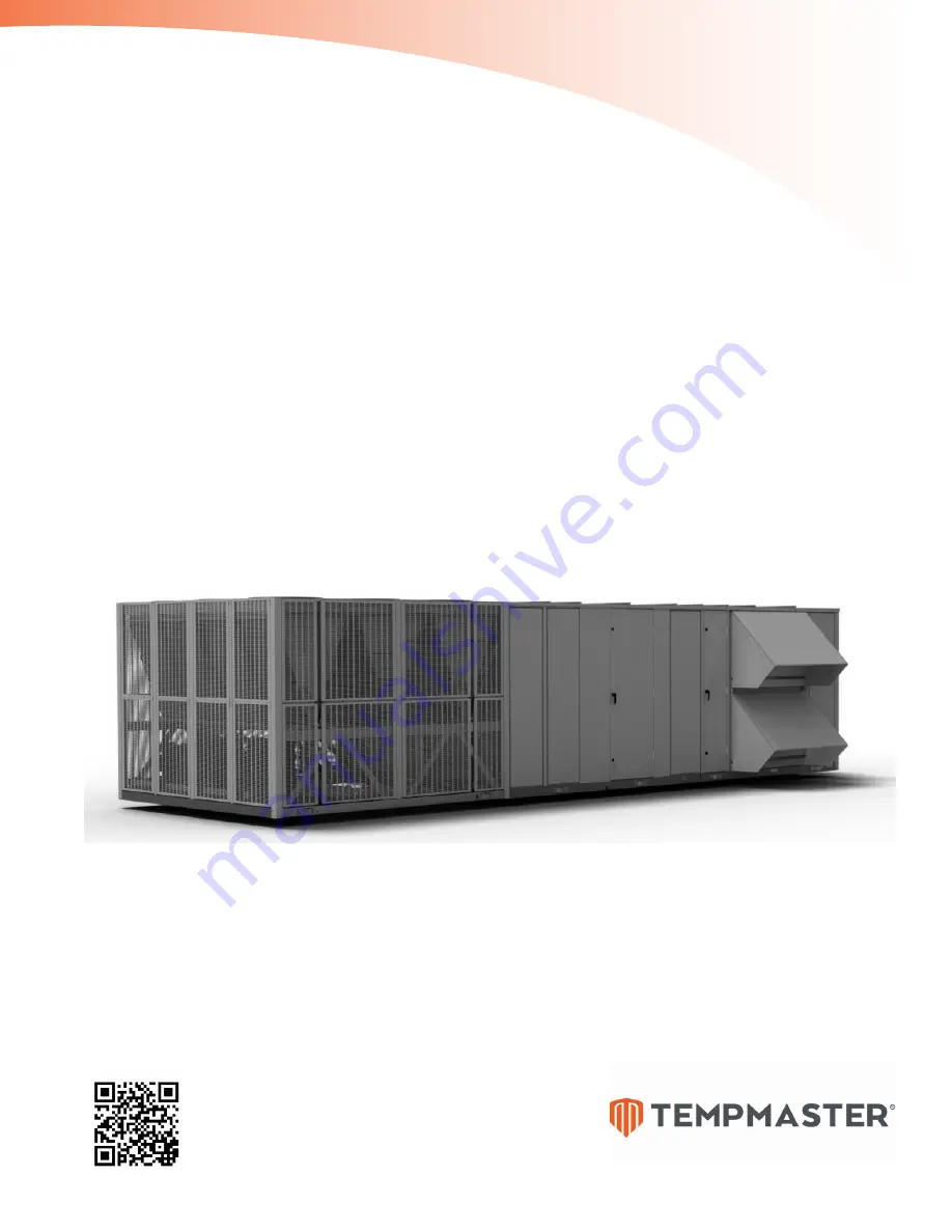
TempMaster
®
OmniElite
™
SINGLE PACKAGE ROOFTOP UNITS
ENGINEERING GUIDE
120–150 Tons
Cooling and Heating (Gas, Electric, Water, and Steam)
R-410A
Mod G
Page 1: ...LD19506 FORM TPM3 EG1 518 TempMaster OmniElite SINGLE PACKAGE ROOFTOP UNITS ENGINEERING GUIDE 120 150 Tons Cooling and Heating Gas Electric Water and Steam R 410A Mod G...
Page 2: ...R 410A 6 460 3 60 8 575 3 60 V VAV or SZVAV B Bottom Return R Rear Return S Side Return C Cooling Only N Natural Gas Heat G Natural Gas Heat Stainless Steel Heat Exchanger M Modulating Gas Heat E Ele...
Page 3: ...TRIC HEAT 38 SUPPLY FAN DATA 39 COMPONENT STATIC PRESSURE DROPS 40 ELECTRIC HEAT PRESSURE DROPS 42 GAS HEAT PRESSURE DROPS 42 EXHAUST FAN DATA 43 RETURN FAN DATA 44 ELECTRICAL DATA 45 CONTROLS 47 POWE...
Page 4: ...TEMPMASTER 4 FORM TPM3 EG1 518 THIS PAGE INTENTIONALLY LEFT BLANK...
Page 5: ...empMas ter OmniElite to be applied to virtually any building application Accessibility through double wall access doors spacious compartments and sup portive floors improves serviceability Better Ecol...
Page 6: ...r fans 3 Scroll compressors 4 Condenser 5 Advanced single package unit controller 6 Evaporator coil 7 Rain hoods 8 Exhaust return fan 9 Economizer 10 Filters section 11 Double wall construction 12 Dou...
Page 7: ...SAT sensor is located across the face of the supply duct opening in the unit Furnaces are designed in 375 mbh modules Three stages are available for the TMAL120 150 Ignition and safety controls are i...
Page 8: ...OmniElite units are equipped with a factory installed programmed and commissioned unit controller with all I O capabilities and control sequences The controls include all on board diagnostic safety an...
Page 9: ...sensor or optional single or comparative enthalpy controls Airflow Measurement Optional outside airflow measurement is available on units equipped with a modulating economizer CO2 Sensors Optional ca...
Page 10: ...oil Supply Fan The standard airfoil blade sup ply fan is available on all models for higher static conditions This offers higher efficiency and lower sound in certain applications Fan Skid Isolation T...
Page 11: ...d so that only two scroll compressors are in tandem within one refrigeration circuit This means more reliable com pressors and less equipment down time With multiple circuits if a compressor should ev...
Page 12: ...irflow from the fan evenly across the downstream filter bank to optimize filter life and effectiveness The diffuser design is optimized to provide uniform flow at minimal airside pressure loss Downstr...
Page 13: ...itioned space Remote keypad in control section In filtered air stream to prevent dust and dirt build up Side discharge with heat Does not require an elevated structure or curb Flexible solution for bu...
Page 14: ...e clearance space of 6 feet around the perimeter of the unit 8 feet on one side for coil servicing and 12 feet to any adjacent units is required to eliminate cross contamination of exhaust and outside...
Page 15: ...cials to ensure the application conforms to local codes and regulations Ground Level Locations It is important that the units be installed on a substantial base that will not settle causing strain on...
Page 16: ...or re entrainment of outside airflow Regardless of the outside air and exhaust air openings on a unit all single package unit applications can permit recirculation of exhaust air to the return if appl...
Page 17: ...d closed TempMaster variable frequency drives VFDs offer superior fan speed control and quieter energy efficient operation Figure 3 TRADITIONAL OVERHEAD VARIABLE AIR VOLUME VAV AIR DELIVERY SYSTEM For...
Page 18: ...sure requirements of the system For normal building pres sure control the exhaust fan operates to draw air from the return plenum and exhaust it out of the building The exhaust fan configuration is av...
Page 19: ...32 32 32 32 32 32 Motor Size Range min to max HP 7 5 60 7 5 60 7 5 60 Airflow Range min to max CFM 0 50000 0 50000 0 50000 Static Pressure Range min to max ESP 0 2 inches 0 2 inches 0 2 inches RETURN...
Page 20: ...x width in inches 12x24 16x20 12x24 16x20 12x24 16x20 16x25 20x20 16x25 20x20 16x25 20x20 20x24 20x25 20x24 20x25 20x24 20x25 Total Filter Face Area sq ft 80 4 80 4 80 4 GAS FURNACE Staged Furnace Siz...
Page 21: ...T AIR HANDLING SECTION Sheet Metal Note 1 6 310 Control Panel Note 2 705 REFRIGERANT Refrigerant Charge R 410A 210 230 230 COMPRESSORS 826 1 661 1 738 CONDENSER ASSEMBLY Sheet Metal 2 477 Coils 864 Co...
Page 22: ...Hood 539 HEATING OPTIONS Electric Heat 80 kW 660 Electric Heat 108 kW 680 Electric Heat 150 kW 700 Electric Heat 200 kW 720 Electric Heat 250 kW 740 Gas Heat 1125 mbh 1 455 Hot Water Coil 2 rows x 14...
Page 23: ...0 649 5 62 1608 8 1577 1 1537 0 1448 8 1536 5 1296 6 1536 2 1074 4 1535 8 852 2 42000 75 1874 6 1257 9 1869 6 1021 4 1869 6 785 5 71 1754 8 1425 1 1753 1 1191 3 1753 1 950 7 1753 1 709 6 67 1692 4 152...
Page 24: ...1486 1 1415 5 1427 3 1245 3 1427 1 1023 5 1426 9 801 7 42000 75 1800 1 1230 7 1797 8 995 0 1797 8 759 5 71 1685 1 1397 6 1684 2 1164 1 1684 2 923 9 1684 2 682 8 67 1632 9 1497 4 1576 3 1329 7 1576 3 1...
Page 25: ...2 1511 7 1505 9 1429 7 1412 4 1367 7 1218 2 1367 7 996 4 1367 7 774 6 42000 75 1722 6 1202 7 1719 5 967 0 1719 5 731 6 71 1614 3 1370 0 1610 0 1135 3 1610 4 895 3 1610 4 654 4 67 1568 8 1459 7 1504 9...
Page 26: ...1372 9 1328 1 1303 3 1187 9 1302 2 972 5 1301 0 757 1 42000 75 1633 4 1171 3 1633 4 936 9 1633 4 701 4 71 1537 1 1340 3 1535 4 1106 7 1528 2 864 0 1528 2 623 3 67 1502 2 1417 0 1430 7 1269 3 1429 8 10...
Page 27: ...62 1398 9 1388 5 1314 9 1283 7 1233 6 1155 9 1233 6 934 6 1233 6 713 4 42000 75 1541 8 1139 4 1538 8 903 8 1533 3 666 8 71 1450 7 1291 0 1445 3 1072 9 1445 3 832 6 1445 3 592 2 67 1433 5 1378 2 1357 2...
Page 28: ...80 9 1577 9 1673 4 1396 7 1670 6 1159 0 1667 8 921 3 42000 75 2086 7 1387 9 2082 8 1125 4 2080 4 867 5 71 1952 2 1566 4 1952 1 1307 0 1942 3 1038 6 1935 8 782 2 67 1848 3 1655 8 1828 9 1481 0 1825 7 1...
Page 29: ...62 1716 8 1683 1 1639 1 1545 8 1596 7 1360 3 1594 4 1122 7 1592 2 885 2 42000 75 2007 8 1358 9 2003 7 1096 5 1998 6 837 7 71 1878 6 1537 1 1876 0 1276 6 1874 4 1012 0 1871 9 757 1 67 1787 3 1618 5 176...
Page 30: ...1575 6 1497 9 1572 7 1348 6 1571 3 1111 5 1569 8 874 4 42000 75 1920 2 1327 5 1916 0 1064 7 1910 9 806 6 71 1795 3 1504 4 1794 3 1244 9 1793 1 980 1 1791 9 725 9 67 1733 6 1512 7 1684 7 1188 8 1681 3...
Page 31: ...62 1599 3 1578 1 1515 1 1452 2 1508 3 1318 5 1506 9 1081 4 1505 5 844 3 42000 75 1826 3 1293 9 1819 5 1030 5 1816 2 772 9 71 1712 3 1472 5 1710 0 1212 3 1708 7 947 8 1703 0 691 9 67 1659 4 1544 0 1601...
Page 32: ...1450 9 1403 3 1440 2 1286 9 1438 9 1049 8 1437 5 812 7 42000 75 1718 9 1256 1 1718 0 994 9 1718 2 738 5 71 1620 6 1437 8 1624 5 1179 9 1621 4 914 3 1616 0 658 8 67 1586 4 1499 8 1518 5 1351 1 1515 4...
Page 33: ...81 1 1843 4 1774 6 1670 5 1775 7 1471 3 1773 7 1229 2 1771 8 987 2 42000 75 2219 1 1458 7 2217 9 1178 0 2217 9 913 0 71 2080 2 1644 7 2082 9 1358 0 2077 1 1094 2 2078 4 836 1 67 1950 7 1746 9 1949 0 1...
Page 34: ...1745 8 1698 9 1701 7 1451 4 1699 9 1201 7 1698 2 951 9 42000 75 2132 9 1413 7 2132 6 1137 0 2129 5 887 1 71 1998 6 1619 7 1995 9 1341 0 1997 6 1084 0 1997 9 814 7 67 1913 6 1777 7 1868 4 1531 0 1864 7...
Page 35: ...62 1770 8 1726 3 1675 7 1594 8 1626 6 1416 0 1624 3 1171 5 1622 0 926 9 42000 75 2033 0 1387 7 2031 9 1101 0 2031 8 836 1 71 1907 0 1579 0 1902 9 1301 0 1899 8 1062 0 1900 6 784 0 67 1835 4 1698 7 17...
Page 36: ...8 1614 1 1584 0 1549 5 1383 9 1546 7 1117 9 1543 8 851 9 42000 75 1928 6 1340 7 1924 5 1064 0 1926 6 799 3 71 1814 5 1535 7 1810 0 1251 0 1810 3 983 7 1810 1 732 6 67 1757 6 1633 5 1700 3 1465 0 1692...
Page 37: ...3 62 1635 5 1618 7 1545 2 1494 7 1468 1 1342 7 1465 9 1093 7 1463 8 844 7 42000 75 1825 3 1308 0 1819 2 1028 0 1817 3 766 9 71 1712 8 1494 7 1708 4 1226 0 1701 3 948 2 1707 1 696 7 67 1681 2 1601 3 16...
Page 38: ...1000 AIRFLOW MINIMUM TEMP RISE F 120 150 1125 900 19350 43 NOTE Gas valve rated for 0 5 psig If gas pressure greater than 0 5 psig then a gas pressure regulator is required Minimum gas pressure is 4...
Page 39: ...2 51 9 1114 62 0 1174 72 5 1230 83 5 52 000 1011 45 5 1079 55 9 1140 66 2 1198 77 0 1254 88 3 Table 13 TMAL120 150 DUAL DIRECT DRIVE PLENUM DDP 330 100 FAN TOTAL STATIC PRESSURE INCHES OF WATER COLUMN...
Page 40: ...58 0 42 0 46 0 45 0 28 0 061 46 000 0 40 0 29 0 66 0 63 0 46 0 51 0 49 0 31 0 067 48 000 0 44 0 31 0 72 0 69 0 50 0 55 0 54 0 34 0 073 50 000 0 47 0 34 0 78 0 75 0 54 0 60 0 59 0 37 0 079 52 000 0 51...
Page 41: ...IGID FILTER TRACK WITH 2 INCH MERV 8 PREFILTERS 12 INCH MERV 11 WITH 2 INCH MERV 8 PREFILTERS 12 INCH MERV 14 WITH 2 INCH MERV 8 PREFILTERS FINAL FILTER 12 INCH MERV 14 120 150T 24 000 0 07 0 02 0 08...
Page 42: ...0 44 40 000 0 12 0 21 0 24 0 29 0 39 0 49 42 000 0 13 0 23 0 27 0 32 0 43 0 54 44 000 0 15 0 25 0 29 0 36 0 47 0 59 46 000 0 16 0 28 0 32 0 39 0 51 0 65 48 000 0 17 0 30 0 35 0 42 0 56 0 71 50 000 0 1...
Page 43: ...329 9 9 351 10 7 377 12 0 405 13 5 430 15 0 453 16 3 30 000 283 9 3 315 10 6 343 11 7 363 12 6 386 13 7 411 15 2 436 16 8 460 18 4 32 000 298 11 1 328 12 4 356 13 8 377 14 8 397 15 7 418 17 0 442 18 7...
Page 44: ...1068 37 2 1083 39 3 1098 41 5 1113 43 8 48 000 1082 37 2 1096 39 4 1111 41 6 1125 43 9 1139 46 2 1154 48 5 50 000 1125 41 9 1140 44 2 1153 46 4 1167 48 8 CFM STD AIR 1 75 2 00 2 25 2 50 2 75 3 00 RPM...
Page 45: ...is the current of the electric heaters Note zero for cooling only units LOAD4 is the sum of any remaining currents greater than or equal to 1 0 amp Use the following calculations to determine MCA and...
Page 46: ...20 24 19 1 20 24 19 2 25 30 24 5 25 31 24 30 36 29 30 38 29 40 49 40 40 48 37 50 57 46 50 58 45 60 68 56 60 67 8 54 4 75 N A N A 75 N A N A 100 N A N A 100 N A N A Table 27 ELECTRICAL HEAT STAGES 120...
Page 47: ...0 E Link for N2 UNOCCUPIED OCCUPIED SWITCHING Depending on the application the unit can be indexed between unoccupied and occupied modes of operation by one of three methods hardwired input internal...
Page 48: ...s insufficient for the cooling load the unit controller shall stage up compressors one at a time to meet de mand The control logic for the three types of economizers is as follows Dry Bulb Economizer...
Page 49: ...to this flow rate as long as the unit is in the occupied mode and the economizer is not suitable for cooling Demand Ventilation If optional carbon dioxide CO2 sensors are connected to the unit the un...
Page 50: ...FD is controlled to maintain a slightly positive pressure over the mixing box section to prevent reverse flow As the return and or exhaust air dampers open the return plenum pressure drops and the fan...
Page 51: ...exhaust return fan VFD to 0 4 Set the OA damper to 100 and the exhaust damper to 0 Evacuation Evacuation shall be used to evacuate negatively pressurize the building or space in or der to draw air th...
Page 52: ...e it to the unoccupied zone heating setpoint The unoccupied zone heating setpoint is set through the setpoints key heating subsec tion of the user interface If zone temperature is equal to or less tha...
Page 53: ...ted mode the input is a serial input from a BAS THERE IS NO DEMAND FOR HEATING BASED ON THE ACTIVE ZONE TEMPERATURE SETPOINT SUPPLY FAN AT SZVAV MINIMUM SETPOINT ZONE TEMPERATURE IS MORE THAN 1 5 F BE...
Page 54: ...ure setpoints These setpoints are user selectable at the user interface When a zone sensor is used for control the unit controller will monitor the temperature within the space and control the unit ac...
Page 55: ...aintenance IOM manual TPM3 NOM1 manual or unit nameplate data to determine minimum circuit ampacities MCAs and recommended dual element fuse sizes 4 MCA is based on U L Standard 1995 Section 36 14 N E...
Page 56: ...al TPM3 NOM1 manual or unit nameplate data to determine minimum circuit ampacities MCAs and recom mended dual element fuse sizes 4 MCA is based on U L Standard 1995 Section 36 14 N E C Section 440 34...
Page 57: ...C COM 24VAC COM SAT SUPPLY AIR TRMP RESET SAT SUPPLY AIR TRMP RESET 1 or Duct Pressure Setpoint Reset Or Supply Fan Sync Command NOTES 1 Wiring shown indicates typical wiring Refer to the Installation...
Page 58: ...1 Wiring shown indicates typical wiring Refer to the IOM manual Form TPM3 NOM1 for more detailed wiring methods and options 2 All wiring is Class 2 low voltage 3 Maximum power available from the 24VA...
Page 59: ...59 TEMPMASTER FORM TPM3 EG1 518 BOTTOM SUPPLY BOTTOM RETURN POWERED RETURN ECONOMIZER ELECTRIC HEAT ANGLED FILTERS Figure 10 GENERAL ARRANGEMENT DRAWING General Arrangement Drawing 120 150 Ton Models...
Page 60: ...TER 60 FORM TPM3 EG1 518 LD08172 LEFT SUPPLY FRONT RETURN POWERED EXHAUST ECONOMIZER GAS HEAT ANGLED FILTERS FIGURE 10 GENERAL ARRANGEMENT DRAWING CON TD General Arrangement Drawing 120 150 Ton Models...
Page 61: ...61 TEMPMASTER FORM TPM3 EG1 518 BOTTOM SUPPLY FRONT RETURN POWERED EXHAUST FAN ECONOMIZER ELECTRIC HEAT ANGLED FILTERS LD08175 FIGURE 10 GENERAL ARRANGEMENT DRAWING CON TD...
Page 62: ...ASTER 62 FORM TPM3 EG1 518 BOTTOM SUPPLY BOTTOM RETURN POWERED EXHAUST ECONOMIZER GAS HEAT ANGLED FILTERS FIGURE 10 GENERAL ARRANGEMENT DRAWING CON TD General Arrangement Drawing 120 150 Ton Models Co...
Page 63: ...oof curbs 4 The TempMaster OmniElite unit does not have a base pan under the condensing section of the unit Field fabricated roof curbs must have a cap on the top of the condensing section of the curb...
Page 64: ...OmniElite unit does not have a base pan under the condensing section of the unit Field fabricated roof curbs must have a cap on the top of the condensing section of the curb to prevent moisture from...
Page 65: ...OTES 1 Location of supply line connection horizontal from economizer corner post in direction of airflow 2 Location of return line connection horizontal from economizer corner post in direction of air...
Page 66: ...TEMPMASTER 66 FORM TPM3 EG1 518 Power Control Entry Drawing 120 150 Ton Models LD19504 Figure 11 POWER CONTROL WIRING LOCATION...
Page 67: ...ed in accordance with the ARI Standard 340 360 4 All units shall be tested to ANSI UL 1995 and CAN CSA C22 2 No 236 standards 5 Gas heating units shall be designed in conformance with ANSI Z21 47 2006...
Page 68: ...nclude dimensions weights capacities ratings fan performance motor electrical characteristics and gauges and finishes of materials Documentation 1 Fan curves with specified operating point clearly plo...
Page 69: ...complete post and panel construction with exterior skin All pan els doors walls uprights floor panels and roofing shall be 1 inch thick 1 1 2 pound den sity insulation Units are specifically designed...
Page 70: ...d in accordance with AMCA Standard 500 and have a longevity of 60 000 damper opening and closing cycles complying with the require ments of California Title 24 SELECT ONE OF THE FOLLOWING TYPES OF BUI...
Page 71: ...an discharge shall be connected to the fan cabinet using a flexible connection to ensure vibration free operation 3 Bearings and Drives Fan bearings shall be self aligning pillow block or flanged type...
Page 72: ...n discharge shall be connected to the fan cabinet us ing a flexible connection to ensure vibration free operation b Bearings and Drives Fan bearings shall be self aligning pillow block or flanged type...
Page 73: ...rol cabinet for accessibility and servicing while the unit is operating Discharge Plenum SELECT ONE OF THE FOLLOWING HEAT NO HEAT CONFIGURATIONS 1 Cooling Only The discharge air temperature DAT sensor...
Page 74: ...rovide secondary airflow safety protection The rollout switch shall discontinue furnace operation if the flue becomes restricted e Flue The furnace flue shall be shipped loose to protect it from damag...
Page 75: ...1 4 inch All header connections shall be of red brass or steel with male pipe threads MPTs and silver braze to headers Casing shall be galvanized steel The core shall be pitched in the direction of t...
Page 76: ...requires to properly operate the unit Upon entering cool ing mode from other modes the unit controller will estimate the cooling requirement and match it closely to the capacity in order to reduce th...
Page 77: ...r and to maintain proper operation The unit shall continue to operate in a trouble mode or shut down as necessary to prevent an unsafe condition for the building occupants or to prevent damage to the...
Page 78: ...weatherproof enclosures VFDs and end devices shall be effectively cov ered for protection against rain snow wind dirt sun fading road salt chemicals rust and corrosion during shipping cycle Equipment...
Page 79: ...79 TEMPMASTER FORM TPM3 EG1 518 NOTES...
Page 80: ...Printed on recycled paper Form TPM3 EG1 518 Supersedes TPM3 EG1 1117 2018 TempMaster P O Box 423 Milwaukee WI 53201 Printed in USA www tempmasterhvac com Issued on 5 11 2018...