background image

DEVICE CONFIGURATION

TECHNICAL INFORMATION

1.

 Power on the device and connect the Ethernet cable to your computer. 

2.

 Allow the gateway to boot up. This might take up to 60 seconds.  

3.

 To enter the gateway Web interface (WebUI), type 

http://192.168.1.1

 into the URL field of your Internet browser.

4.

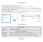
 Use login information shown in image A when prompted for authentication.

5.

 After you log in, you will be prompted to change your password for security reasons. The new password must contain at least 8 characters, 

including at least one uppercase letter, one lowercase letter and one digit. This step is mandatory, and 

you will not be able to interact with 

the gateway WebUI until you change the password.

6.

 When you change the gateway password, the 

Configuration Wizard

 will start. The 

Configuration Wizard

 is a tool used to set up some of the 

gateway main operating parameters.

7.

 Go to the 

Overview

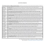
 page and pay attention to the 

Signal Strength

 indication (image B). To maximize the cellular performance try adjusting 

the antennas or changing the location of your device to achieve the best signal conditions.

*Order code dependent.

**Higher gain antenna can be connected to compensate for cable attenuation when a cable is used. The user is responsible for the compliance with the legal regulations.

Radio specifications

Bundled accessories specifications*

RF technologies

Max RF power

EGPRS, NB-IoT, LTE (Cat-M1), GNSS

33 dBm@GSM, 23 dBm@LTE 

Power adapter

Input: 0.4 A@100-240 VAC, output: 9 VDC, 1 A, connected to 16 pin terminal block

Mobile antenna

698~960 / 1710~2690 MHz, 50 Ω, VSWR < 3, gain** 3 dBi, omnidirectional, SMA male connector

A.

B.

Bytes received/sent

SIM card slot in use

Data connection

State

-65 dBm

Connected

Registered (home); OPERATOR; 4G (LTE)

Ready

348.7 KB / 223.5 KB

admin

admin01

GNSS antenna

1575.42~1602 MHz, 2.2~5 VDC, VSWR < 1.5, gain** 28 dB (typ.), RHCP polarization, SMA male connector

Summary of Contents for TRB255

Page 1: ...Quick Start Guide v1 2 https wiki teltonika networks com ...

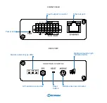
Page 2: ...FRONT VIEW Mobile network type LEDs BACK VIEW Power LED Mobile signal strength indication LEDs Reset button Input output connector GPS antenna connector Mobile antenna connector Ethernet port ...

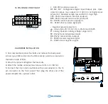
Page 3: ...TALLATION 16 PIN CONNECTOR PINOUT SIM1 SIM2 9 30 VDC positive power pin D1 D2 D3 Configurable digital Input Output pins Open collector output max output 30 V 300 mA or Digital input where 0 6 V detected as logic low and 8 30 V logic high CTS RS232 clear data to send pin output RTS RS232 request data to send pin input R RS485 receiver positive signal pin D RS485 driver positive signal pin Negative g...

Page 4: ...gateway main operating parameters 7 Go to the Overview page and pay attention to the Signal Strength indication image B To maximize the cellular performance try adjusting the antennas or changing the location of your device to achieve the best signal conditions Order code dependent Higher gain antenna can be connected to compensate for cable attenuation when a cable is used The user is responsible...

Page 5: ...5 ΣΥΜΜΟΡΦΩΝΕΤΑΙ ΠΡΟΣ ΤΙΣ ΟΥΣΙΩΔΕΙΣ ΑΠΑΙΤΗΣΕΙΣ ΚΑΙ ΤΙΣ ΛΟΙΠΕΣ ΣΧΕΤΙΚΕΣ ΔΙΑΤΑΞΕΙΣ ΤΗΣ ΟΔΗΓΙΑΣ RED HU Hungarian A TELTONIKA ezzennel kijelenti hogy a TRB255 típusú berendezés teljesíti az alapvető követelményeket és más RED irányelvben meghatározott vonatkozó rendelkezéseket IT Italian Con la presente TELTONIKA dichiara che questo TRB255 è conforme ai requisiti essenziali ed alle altre disposizioni p...

Page 6: ...mentazione per accendere l unità Aprire 192 168 1 1 in un browser Web per configurare il prodotto Maggiori informazioni in https wiki teltonika networks com LT Naudojimosi instrukcija Prijunkite maitinimo adapterį įjunkite įrenginį Interneto naršyklėje atidarykite adresą 192 168 1 1 galite konfigūruoti gaminį Daugiau informacijos rasite https wiki teltonika networks com LV Lietošanas instrukcija Pie...

Reviews: