


11
4.2.2.
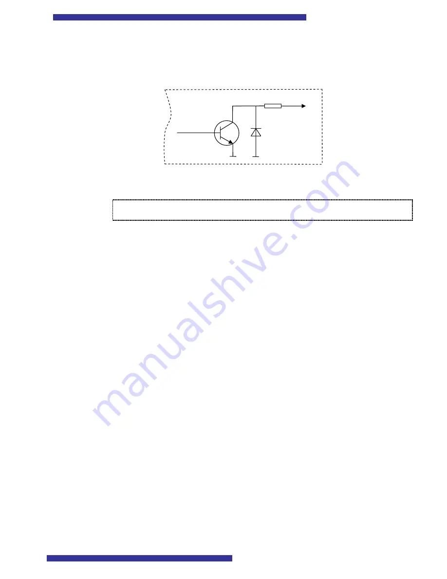
Digital Outputs
T-BoxN12R has open collector outputs. The picture below shows the internal circuit
diagram of outputs implementation:
Outputs can drive up to 70mA or 200mW load. The circuit has protection diode so
outputs can directly drive relays.
Note: When T-BoxN12R operates in AT mode (switch is in position “AT”)
outputs 2,3,4,5 and Inputs 5 and 6 are disabled!
4.2.3.
Analog Inputs
Analog inputs are designed to measure voltage in range from 0 to 10 V. As this input
voltage is internally divided by 2,8, the measured values by Nokia 12 will be vary from 0 to
2,7 V.
The analog inputs have protection diodes, which protect the device from too high
voltage and negative voltage.
4.3.
Serial communication
T-BoxN12R provides 3 serial communication ports:
Serial port 1. Connected to Nokia 12 port 1. This port can be used for AT
commands, GPS or as system port.
Serial port 2. Connected to Nokia 12 port 2. This port can be used as system port
(M2M protocol to configure Nokia 12) only
Serial port 3. Connected to Nokia 12 Port 3. This port is controlled by Java
application on the Nokia 12 module or GPS.
There are only two RJ45 serial port connectors on the housing, which are marked as
PORT1 and PORT2/3. As you can see, PORT2 and PORT3 share the same connector.
This, at first glance unusual, solution was made, because usually PORT2 is used for device
configuration only and is not used during normal operation.
The package contains two serial cables, marked as “PORT 1/2” and “PORT3”.
Refer to
Table 3
to choose the right cable and the right connector for the desired serial
port.
10Ω
Output


