ZE51/61-2.4 RF Module User Guide
1VV0300868
Rev.4 – 23/06/201
1
Reproduction forbidden without Telit Communications S.p.A. written authorization - All Rights Reserved
page 39 of 54
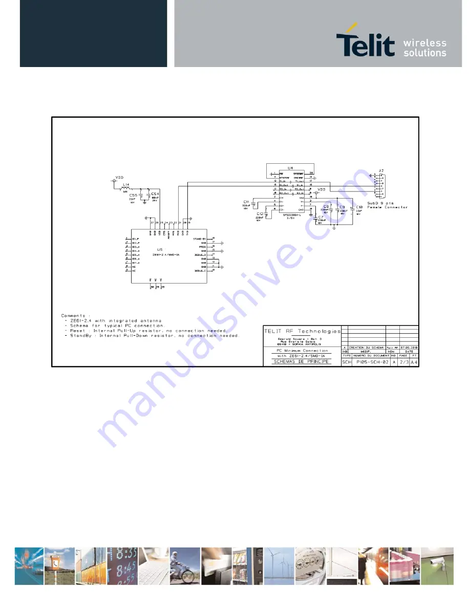
Example of a minimum PC connection with
ZE51/61-2.4/SMD-IA .
Page 1: ...ZE51 61 2 4 RF Module User Guide 1VV0300868 Rev 4 23 06 2011...
Page 2: ...RF module User Guide 1VV0300868 Rev 4 23 06 2011 Reproduction forbidden without Telit Communications S p A written authorization All Rights Reserved page 2 of 54 This document is related to the follow...
Page 3: ...injury loss or damage of any kind incurred by use of or reliance upon the information Telit disclaims any and all responsibility for the application of the devices characterized in this document and...
Page 4: ...ERISTICS 14 III 1 MECHANICAL CHARACTERISTICS 14 III 2 MECHANICAL DIMENSIONS 15 III 3 DC CHARACTERISTICS 16 III 4 FUNCTIONAL CHARACTERISTICS 17 III 5 DIGITAL CHARACTERISTICS 20 III 6 ABSOLUTE MAXIMUM R...
Page 5: ...ONS 36 VI 4 ANTENNA CONNECTION ON PRINTED CIRCUIT BOARDS 37 VI 5 ZE51 61 2 4 INTERFACING 38 CHAPTER VII ANTENNA CONSIDERATIONS 41 VII 1 ANTENNA RECOMMENDATIONS 41 VII 2 ANTENNA MATCHING 42 VII 3 ANTEN...
Page 6: ...ns I 2 Contact Information Support For general contact technical support to report documentation errors and to order manuals contact Telit Technical Support Center TTSC at TS SRD telit com TS NORTHAME...
Page 7: ...Amending Decision 2006 771 EC on harmonization of the radio spectrum for use by short range devices 11 SR Manager Tool User Guide 1vv0300899 12 ZigBee PRO Democase Getting Started 1vv0300901 13 ZigBe...
Page 8: ...Read Only Memory ERC European Radiocommunications Committee ETR ETSI Technical Report ETSI European Telecommunication Standard Institute FCC Federal Communications Commission IEEE Institute of Electri...
Page 9: ...spacing specified No restriction Annex 3a Wideband Data Transmission systems 2400 2483 5 MHz 100 mW e i r p and 100 mW 100 kHz e i r p density applies when frequency hopping modulation is used 10 mW...
Page 10: ...own premises For public use a general authorization is required Ukraine Limited Implemented e i r p 100 mW with built in antenna with amplification factor up to 6 dBi Norway Implemented This subsecti...
Page 11: ...the product must be declared in compliance with the harmonized ETSI standards EN 300 440 Class 1h or EN 300 228 Class 3a Finally the module complies with the new European Directive 2002 95 EC concerni...
Page 12: ...d pre flashed with Telit in house ZigBee PRO stack Please refer to ZigBee PRO Protocol Stack User Guide 8 for detail information In case the customer needs to develop his own software different tools...
Page 13: ...production forbidden without Telit Communications S p A written authorization All Rights Reserved page 13 of 54 II 4 Temperature Requirements Minimum Typical Maximum Unit Operating Temperature 40 25 8...
Page 14: ...GENERAL CHARACTERISTICS III 1 Mechanical Characteristics Size Rectangular 26 x 15 mm Height 3 mm Weight 1 7 g PCB thickness 0 8 mm Cover Dimensions 21 x 14 x 2 2mm Thickness 200 m Components All SMD...
Page 15: ...E51 61 2 4 RF Module User Guide 1VV0300868 Rev 4 23 06 2011 Reproduction forbidden without Telit Communications S p A written authorization All Rights Reserved page 15 of 54 III 2 Mechanical dimension...
Page 16: ...ristics ZE51 Min Typ Max Power Supply VDD 2 0V 3 6V Transmission 35mA 39mA Reception 26mA 29mA Stand by 32 768 khz On 2 A 2 7 A Sleep wake up on interruption 1 A I O low level GND 0 9 V I O high level...
Page 17: ...S Modulation O QPSK with half sine pulse shaping Radio bit rate 250 kbps Transmit chip rate 2 Mchip s Transmission ZE51 Min Typ Max Output Power 4dBm 1 dB on the whole band selectable by software Harm...
Page 18: ...put power for different power settings Reception ZE51 Min Typ Max Sensitivity for PER 1 96 dBm 97 dBm Saturation for PER 1 10 dBm Adjacent channel rejection 5 MHz channel spacing 49 dB Wanted signal 8...
Page 19: ...nel rejection 5 MHz channel spacing 49 dB Wanted signal 82 dBm adjacent modulated channel 5 MHz for PER 1 Alternate channel rejection 10 MHz channel spacing 54 dB Wanted signal 82 dBm adjacent modulat...
Page 20: ...rity 1 or 2 stop bits Protocol Type RS 232 TTL level Flow control Managed by application None Software Xon Xoff or Hardware RTS CTS Other Ultra low power voltage detector and C supervisory circuit Spe...
Page 21: ...51 Voltage applied to VDD 0 3V to 3 9V Voltage applied to any digital pin 0 3V to VDD 0 3V max 3 9 V Input RF level 10 dBm ZE61 Voltage applied to VDD 0 3V to 3 6V Voltage applied to any digital pin 0...
Page 22: ...The USB dongle The Demo Case The versions below are considered standard and should be readily available For other versions please contact Telit Please make sure to give the complete part number when...
Page 23: ...le User Guide 1VV0300868 Rev 4 23 06 2011 Reproduction forbidden without Telit Communications S p A written authorization All Rights Reserved page 23 of 54 CHAPTER IV TECHNICAL DESCRIPTION IV 1 Pin ou...
Page 24: ...XD O TTL TxD UART Serial Data Transmission J18 STAND_BY I TTL Standby Active high with internal pull down J17 GND Gnd Ground J16 PROG I TTL Signal for serial C flashing Active high with internal pull...
Page 25: ...RF Module User Guide 1VV0300868 Rev 4 23 06 2011 Reproduction forbidden without Telit Communications S p A written authorization All Rights Reserved page 25 of 54 IV 2 DIP Module mechanical dimensions...
Page 26: ...P3 9 P1_1 6 J1 P4 11 P1_0 7 J4 P5 16 P0_3 8 J3 P6 17 P0_2 9 GND GND 10 J25 VDD AVDD DVDD J2 11 J16 PROG 36 P2_0 12 J22 RTS 7 P1_3 13 J24 CTS 8 P1_2 14 J23 Reset 20 Reset_N 15 J21 RxD 6 P1_4 16 J19 Tx...
Page 27: ...ls format NRZ TTL TXD is for outgoing data RXD is for incoming data The 1 is represented by a high state CTS Incoming signal Indicates whether the module can send serial data to user Active on low sta...
Page 28: ...hts Reserved page 28 of 54 CHAPTER V PROCESS INFORMATION V 1 Delivery ZE51 61 2 4 SMD modules are delivered in plastic tray packaging each tray including 50 units The dimensions of the tray are the fo...
Page 29: ...ing 24 hours The drying bake must be used prior to the reflow soldering process in order to prevent a popcorn effect After being submitted to the drying bake tiny modules must be soldered on host boar...
Page 30: ...munications S p A written authorization All Rights Reserved page 30 of 54 The recommended soldering pad layout on the host board for the ZE51 61 2 4 SMD IA is shown in the diagram below All dimensions...
Page 31: ...moon solder joints see diagram below For proper module assembly solder paste must be printed on the target surface of the host board The solder paste should be eutectic and made of 95 5 of SN 4 of Ag...
Page 32: ...f 54 V 6 Soldering profile RoHS process It must be noted that ZE51 61 2 4 SMD module should not be allowed to be hanging upside down during the reflow operation This means that the module has to be as...
Page 33: ...eserved page 33 of 54 The barcode label located on the module shield is able to withstand the reflow temperature CAUTION It must also be noted that if the host board is submitted to a wave soldering a...
Page 34: ...nces of the ZE51 61 2 4 module are obtained in a clean noise environment Some basic recommendations must be followed Noisy electronic components serial RS232 DC DC Converter Display Ram bus must be pl...
Page 35: ...of 54 VI 2 Power supply decoupling on ZE51 61 2 4 module The power supply of ZE51 61 2 4 module must be nearby decoupled A LC filter must be placed as close as possible to the radio module power supp...
Page 36: ...ith ground plane except in case of integrated antenna no ground plane must be placed in front of the antenna and on the bottom side The radio module ground pin must be connected to solid ground plane...
Page 37: ...the antenna or connector must be 50 ohms following the tables below Ground lines should be connected to the ground plane with as many vias as possible but not too close to the signal line PCB material...
Page 38: ...4 23 06 2011 Reproduction forbidden without Telit Communications S p A written authorization All Rights Reserved page 38 of 54 VI 5 ZE51 61 2 4 interfacing Example of a full RS 232 connection between...
Page 39: ...dule User Guide 1VV0300868 Rev 4 23 06 2011 Reproduction forbidden without Telit Communications S p A written authorization All Rights Reserved page 39 of 54 Example of a minimum PC connection with ZE...
Page 40: ...module User Guide 1VV0300868 Rev 4 23 06 2011 Reproduction forbidden without Telit Communications S p A written authorization All Rights Reserved page 40 of 54 Example for sensor connection with ZE51...
Page 41: ...type and its location Particular cautions are required on the following points Use a good and efficient antenna designed for the 2 4 GHz band Antenna must be fixed in such a location that electronic n...
Page 42: ...Symbols Reference Package Value Comments Z1 Resistor 0603 0 ohm ZE51 2 4 DIP WA Monolithic Ceramic capacitor COG 0603 1 5 pF ZE61 2 4 DIP WA Z2 Z3 Not mounted ZE51 2 4 DIP WA Not mounted ZE61 2 4 DIP...
Page 43: ...be used as long as they are adapted to 2 4 GHz frequency Best range may be achieved if the Wave antenna is placed perpendicular in the middle of a solid ground plane measuring at least 5 cm radius In...
Page 44: ...nopole antenna typically offers a ground independent design with favorable gain excellent radiation pattern It has a high impedance and requires an impedance matching circuit See paragraph IX 3 WARNIN...
Page 45: ...basic recommendations are The radio module must not be placed in a metallic casing or close to metallic devices The internal antenna must be far from noisy electronic Ceramic antenna Ceramic antenna...
Page 46: ...6 of 54 ZE51 2 4 SMD IA Integrated antenna ZE51 2 4 module is available with an integrated chip antenna allowing very compact integration for small space application Radiation Pattern of ZE51 2 4 DIP...
Page 47: ...und plane around and below the antenna so ZE61 2 4 SMD IA must be implemented as described in paragraph VI 3 and schematics VI 5 X Y Z Test EU Rotation RADIATION PATTERN Horizontal plane X Y 10 00 5 0...
Page 48: ...module User Guide 1VV0300868 Rev 4 23 06 2011 Reproduction forbidden without Telit Communications S p A written authorization All Rights Reserved page 48 of 54 CHAPTER VIII ANNEXES VIII 1 Declaration...
Page 49: ...ZE51 61 2 4 RF Module User Guide 1VV0300868 Rev 4 23 06 2011 Reproduction forbidden without Telit Communications S p A written authorization All Rights Reserved page 49 of 54...
Page 50: ...ZE51 61 2 4 RF module User Guide 1VV0300868 Rev 4 23 06 2011 Reproduction forbidden without Telit Communications S p A written authorization All Rights Reserved page 50 of 54...
Page 51: ...ZE51 61 2 4 RF Module User Guide 1VV0300868 Rev 4 23 06 2011 Reproduction forbidden without Telit Communications S p A written authorization All Rights Reserved page 51 of 54...
Page 52: ...and receiver Connect the equipment into an outlet on a circuit different from that to which the receiver is connected Consult the dealer or an experienced radio TV technician for help Wireless notice...
Page 53: ...the device into which the module is installed will display a label referring to the enclosed module by labelling the host device in this manner Contains FCC ID RI7ZE51 and IC ID 5131A ZE51 or Contains...
Page 54: ...page 54 of 54 VIII 4 Output power programming The results are measured on the ZE61 2 4 DIP interface with T 25 C Vdd 3 V 2440 Mhz 50 ohm impedance if nothing else noted TxPower register ATS202 Power...