16
en | Maintenance
2020-07 | 01 | F.01U.387.060
Customer Maintenance Manual
Bosch Security Systems, LLC
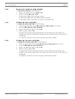
5.4.2
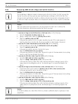
Measure the resistance (plug to PCBA)
To
measure the resistance
, do the following:
1.
Using an ohmmeter, place one
probe on J5
.
2.
Place the other
probe on J6 or J17
.
If measured at 300Ω ±20%, continuity is good.
If measured at 600Ω, one of the speaker paths is defective.
If measured at 270Ω or less, there is a short in the speaker path.
5.4.3
Validate the boom side PCBA
To
validate the boom side PCBA
, do the following:
1.
On the boom side PCBA, send a
1kHz sine wave, 1Vrms signal
from J5 to J6.
2.
Verify the
ANR switch is in the off position
.
3.
Using an oscilloscope, place a probe at
J13
.
4.
Place the other probe at
J14
.
If a signal is found, the board is good and if no sound is heard from the speaker, the
speaker or wiring is bad. Determine if the speaker needs to be replaced or the wires nee
re-soldering.
If a signal is not found, the board is not good and should be replaced.
5.4.4
Validate the non-boom side PCBA
To
validate the non-boom side PCBA
, do the following:
1.
On the non-boom side PCBA, send a
1kHz sine wave, 1Vrms signal
from J5 to J6.
2.
Verify the
ANR switch is in the off position
.
3.
Using an oscilloscope, place a probe at
J13
.
4.
Place the other probe at
J14
.
If a signal is found, the board is good and if no sound is heard from the speaker, the
speaker or wiring is bad. Determine if the speaker needs to be replaced or the wires nee
re-soldering.
If a signal is not found, the board is not good and should be replaced.


