background image

CONTENTS

LIST OF FIGURES

Contents

1

Introduction . . . . . . . . . . . . . . . . . . . . . . . . . . . . . . . . . . . . . . . . . . . . . . . . . . .

2

1.1

Disclaimer . . . . . . . . . . . . . . . . . . . . . . . . . . . . . . . . . . . . . . . . . . . . . . . . .

2

1.2

Description . . . . . . . . . . . . . . . . . . . . . . . . . . . . . . . . . . . . . . . . . . . . . . . .

2

1.3

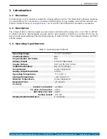
Operating Specifications . . . . . . . . . . . . . . . . . . . . . . . . . . . . . . . . . . . . . . .

2

1.4

Safety Information . . . . . . . . . . . . . . . . . . . . . . . . . . . . . . . . . . . . . . . . . . .

3

1.5

Dimensions . . . . . . . . . . . . . . . . . . . . . . . . . . . . . . . . . . . . . . . . . . . . . . . .

4

2

Setup . . . . . . . . . . . . . . . . . . . . . . . . . . . . . . . . . . . . . . . . . . . . . . . . . . . . . . .

4

2.1

Installation . . . . . . . . . . . . . . . . . . . . . . . . . . . . . . . . . . . . . . . . . . . . . . . .

4

2.2

Electrical Information . . . . . . . . . . . . . . . . . . . . . . . . . . . . . . . . . . . . . . . . .

5

2.3

Calibration . . . . . . . . . . . . . . . . . . . . . . . . . . . . . . . . . . . . . . . . . . . . . . . .

5

2.4

Analog Output . . . . . . . . . . . . . . . . . . . . . . . . . . . . . . . . . . . . . . . . . . . . . .

6

3

Part Numbers . . . . . . . . . . . . . . . . . . . . . . . . . . . . . . . . . . . . . . . . . . . . . . . . . .

7

List of Tables

1

Operating Specifications . . . . . . . . . . . . . . . . . . . . . . . . . . . . . . . . . . . . . . . . . .

2

2

Controller, Cable, and Sensor Part Numbers . . . . . . . . . . . . . . . . . . . . . . . . . . . . . .

7

List of Figures

1

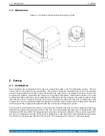
Compact 2A Dimensional Drawing (inches) . . . . . . . . . . . . . . . . . . . . . . . . . . . . . .

4

2

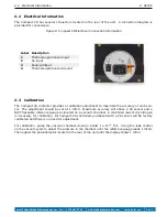
Compact 2A Electrical Connection Information . . . . . . . . . . . . . . . . . . . . . . . . . . . .

5

3

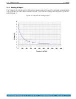
Compact 2A Analog Output . . . . . . . . . . . . . . . . . . . . . . . . . . . . . . . . . . . . . . . .

6

email: [email protected]

tel: +1 215 947 2500

web: frederickscompany.com

comp_2a_im rev -

1 of 7

Summary of Contents for Compact 2A

Page 1: ...ct 2A Thermocouple Controller Instruction Manual The Fredericks Company Televac 2400 Philmont Avenue Huntingdon Valley PA 19006 web www frederickscompany com email sales frederickscompany com tel 1 215 947 2500 fax 1 215 947 7464 ...

Page 2: ...ical Information 5 2 3 Calibration 5 2 4 Analog Output 6 3 Part Numbers 7 List of Tables 1 Operating Specifications 2 2 Controller Cable and Sensor Part Numbers 7 List of Figures 1 Compact 2A Dimensional Drawing inches 4 2 Compact 2A Electrical Connection Information 5 3 Compact 2A Analog Output 6 email sales frederickscompany com tel 1 215 947 2500 web frederickscompany com comp_2a_im rev 1 of 7 ...

Page 3: ... that indicates pressure in units of mTorr The Compact 2A has a 0 10 Volt analog output 1 3 Operating Specifications Table 1 Operating Specifications Operating Range 1 10 3 to 20 Torr Communications N A Programmable Set Points N A Analog Output 0 to 10 V Non linear Supply Voltage 90 V to 135 V AC 60 Hz Calibration Medium Dry air or nitrogen Overpressure Sensor dependent Analog Output Resolution 12...

Page 4: ...trument Televac disclaims all liability for the customer s failure to comply with these requirements READ instructions Read all safety and operating instructions before operating the product RETAIN instructions Retain the Safety and Operating Instructions for future reference HEED warnings Adhere to all warnings on the product and in the operating instructions FOLLOW instructions Follow all operat...

Page 5: ...end of the Compact 2A cable into the port on the back of the Compact 2A It is recommended that the ground connector on the cable is also connected to the port on the back of the Compact 2A labeled with the universal earth ground symbol Try to avoid connecting the 2A sensor to the vacuum chamber by long or narrow piping as this may affect the accuracy and response time of the unit Avoid mounting th...

Page 6: ...t at 1 mTorr Maximum accuracy will utilize a 2A sensor and a NIST traceable reference gauge co located on a vacuum chamber A controlled leak of dry nitrogen is necessary for calibration All Compact 2A controllers purchased with a 2A sensor will be factory calibrated and there is no need for adjustment For calibration pump the vacuum chamber down to below 1 10 4 Torr Using the leak control on the v...

Page 7: ...utput for use with voltmeters programmable logic controllers or other data acquisition devices To convert the analog output signal to a pressure refer to Figure 3 Figure 3 Compact 2A Analog Output email sales frederickscompany com tel 1 215 947 2500 web frederickscompany com comp_2a_im rev 6 of 7 ...

Page 8: ...nless Steel 8 VCR Female 2 2126 043 2A Sensor Stainless Steel 4 VCR Male 2 2126 044 2A Sensor Stainless Steel 4 VCR Female 2 2126 045 2A Sensor Stainless Steel 1 33 CF DN16 ISO CF F 2 2126 050 2A Sensor Stainless Steel 2 75 CF DN40 ISO CF F 2 2126 052 3 ft Cable 2 9800 076 10 ft Cable 2 9800 077 20 ft Cable 2 9800 078 35 ft Cable 2 9800 079 50 ft Cable 2 9800 080 35 ft Cable 2 9800 079 2A Mini Coi...

Reviews: