background image

Installation

5

5

Installation

Wall mounting

For wall mounting the back panel of this 

unit is equipped with 4 screw holes. A VESA 
wall-mount bracket should be used for wall 
mounting (the bracket is not included and 
should be acquired separately). Manufacturer 
is not responsible for improper mounting 
resulting in damage of the unit.

 Due to construction peculiarities, it is not 

recommended to mount TVs on walls using 
swinging and tilting brackets. Such a mounting 
may not be steady

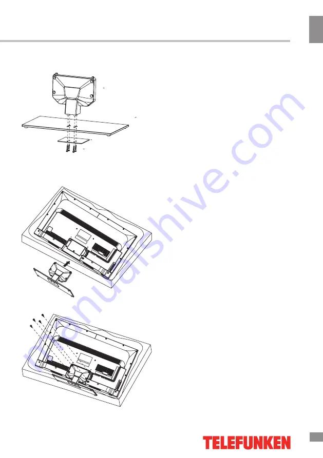
Base instalation (TF-LED40S13):

Connect the base and the stand with four 

4x30 screws.

Next, align this assembly with the holes on 

the back of the unit.

Fix with four M4x10 screws.

Summary of Contents for TF-LED32S13

Page 1: ...Table of contents 3 LED TV c TF LED32S13 TF LED40S13 Instruction manual...

Page 2: ...eletext operations OSD operation Picture Sound Installation Setup Time Advanced USB operation General playback information Operations of file playback General information Troubleshooting Causes of int...

Page 3: ...rts when the unit is unused for long periods of time When unplugging the plug always hold the wide slot do not touch the metal part and do not destroy twist pull or heat the power cord Please contact...

Page 4: ...sport the unit with the power cord or the connection cable connected as it may damage the power cord connection cable or connection terminal which may cause fire electric shock or breakdown Make sure...

Page 5: ...quired separately Manufacturer is not responsible for improper mounting resulting in damage of the unit Due to construction peculiarities it is not recommended to mount TVs on walls using swinging and...

Page 6: ...ct the PC to the VGA jack from the monitor using the VGA cable not included This unit has PC audio in jack Connect this jack to PC main unit with related audio cable in PC mode and adjust the volume t...

Page 7: ...Installation 7 Installation...

Page 8: ...Speakers 3 PROGRAM UP DOWN buttons 4 VOLUME UP DOWN buttons 5 MENU button 6 SOURCE button 7 STANDBY button Back panel 1 HDMI1 2 3 inputs 2 PC VGA input 3 PC audio input 4 Antenna input 5 S PDIF outpu...

Page 9: ...sound volume 17 PROGRAM UP DOWN Select the next previous channel 18 NICAM Select the sound output Mono Stereo NICAM depending on the broadcasting channel 19 SLEEP Select the period after which the TV...

Page 10: ...nd modes from the following types Standard Music Film News Personal Press NICAM button in TV mode repeatedly to switch between Stereo Mono Dual I Dual I II and Dual II sound modes can be unavailable f...

Page 11: ...ss Color Sharpness Tint adjust the tone of color when your system is in NTSC Color Temperature Neutral Warm Cool Display mode 16 9 4 3 Auto Panorama Just Scan Caption Movie DNR select between four mod...

Page 12: ...language of the OSD menu TTX Language select the language of the Teletext PVR File System Personal Video Record setting A USB storage device is required to enable program recording Sticker Demo Show...

Page 13: ...AVI MKV MPG extension with video codecs WMV9 DIVX H263 MPEG 4 MPEGII XVID and audio codecs WMA MP3 DD AC3 The above list of extensions and codecs is for information only and is not a guarantee that a...

Page 14: ...s button to stop playback When you select a file to play you can delete the selected file by pressing Red button on the RC When playing music files you can press buttons to fast reverse or forward You...

Page 15: ...ound No audio signal or the signal cord is improperly not connected Connect the audio signal cord properly Set the sound system properly The RC does not work Batteries are improperly installed or exha...

Page 16: ...100 analog 400 digital Teletext 1000 pages Electric shock protection class II Nominal voltage range 100 240 V 50 60 Hz Power consumption of the LED TV 45 W 70 W Unit dimensions mm without stand 732 x...

Page 17: ...17 15 USB 17 18 18 18 20 20 20 21 21 21 22 22 22 22 23 23 24 24 24 25 25 25 26 26 26 27 27 27 28 29 29 29 30 30...

Page 18: ...18 16 220...

Page 19: ...19 17 LCD 10 18 2...

Page 20: ...20 18 TF LED32S13 4x16 4x30 M3 5X16 4x10 TF LED40S13 4 VESA...

Page 21: ...21 19 75 DVD CAMCORDER Left Right Y Video RCA Y Pb Pr Left Right VGA VGA VGA HDMI HDMI HDMI HDMI2 MHL MHL S PDIF 5 1 75 75...

Page 22: ...22 20 1 2 3 PROGRAM UP DOWN 4 VOLUME UP DOWN 5 MENU 6 SOURCE 7 STANDBY 1 HDMI1 2 3 2 VGA 3 4 5 S PDIF 6 7 Y Pb Pr 8 9 USB1 2...

Page 23: ...ETURN 8 QUICK 9 MENU 10 SOURCE 11 12 OK 13 EXIT 14 INFO 15 3D 16 VOLUME UP DOWN 17 PROGRAM UP DOWN 18 NICAM Mono Stereo NICAM 19 SLEEP 20 Subtitle 21 EPG EPG DTV 22 FAV OK 23 REC 24 FREEZE 25 PLAY PAU...

Page 24: ...OWER VOL VOL RETURN MUTE TV PR PR 0 9 P M S M NICAM Stereo Mono Dual I Dual I II Dual II FREEZE FAV SOURCE PR UP PR DOWN TV AIR DTV AV YPBPR HDMI1 HDMI2 MHL HDMI3 PC USB OK STANDBY TV PR PR HOLD INDEX...

Page 25: ...25 23 1 MENU 2 VOL UP DOWN 3 PR UP DOWN 4 OK STANDBY 5 VOL UP DOWN PR UP DOWN 6 MENU EXIT DNR NTSC 16 9 4 3 Just Scan Caption DNR SPDIF breaks or channel change SPDIF...

Page 26: ...26 24 DTV ATV DTV ATV DTV PVR PVR PVR Personal Video Record USB 10 20 30 60 90 120 180 240 4 6 8...

Page 27: ...27 25 0000 8899 c USB USB USB USB ENTER USB ENTER USB USB 2 0 FAT16 FAT32 1 USB ASF AVI MKV MPG WMV9 DIVX H263 MPEG 4 MPEGII XVID WMA MP3 DD AC3 AVI AVI 2 USB 1 1 2 0 USB 500 USB USB...

Page 28: ...28 26 USB USB BIN OK OK OK INFO OK REPEAT EXIT...

Page 29: ...29 27 VGA...

Page 30: ...30 28 1 1 2 1 3 2 4 1 5 1 6 3 8 7 1 8 1 9 1 31 5 80 39 5 100 1366 x 768 1920 x 1080 16 9 10 8 5 PAL SECAM B G DK I NICAM 2 x 8 RCA VGA HDMI 3 SPDIF...

Page 31: ...31 29 MHL PVR 3D 100 400 USB 1000 II 100 240 50 60 45 70 732 x 60 x 432 900 7 x 60 1 x 517 4 732 x 196 x 474 900 7 x 220 x 558 2 5 7 11 TF LED32 40S13_IM_01...

Reviews: