


TSA-200 / TSA-200XT / TSA-240 / TSA-240XT
© 2010 –
2014 Telefire Fire & Gas Detectors Ltd
Revision 1.06 July 2014
Page 26 of 79
9.3.3 Inputs Wiring
Inputs wiring for detectors and push buttons shall be with a two-wire cable according to
the applicable regulations.
In industrial installations which have machines which produce high power
electromagnetic fields, use shielded cables.
Detector and input wiring shall be in a separate conduit from mains conduit.
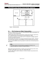
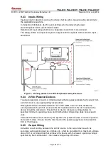
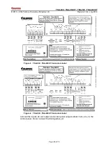
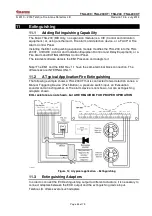
The wiring cables and input and system output shall be separate from mains AC input –
see below
Figure 4 Routing cables in the TSA-200 product family Enclosure
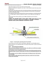
9.3.4 24Vdc Powered Devices
To ensure operation of alarm or initiating device that requires relatively high current from
a 24 Vdc source, use appropriately sized cables.
Wire specifications should be between 12 and 18 AWG, and the cable resistance
running between the 24 Vdc source to the I/O module and from the I/O module to the
device should be calculated. Ensure that no device receives a voltage below its
specified minimum operating value, and that the total voltage drop does not exceed 3
volts.
Calculate the total current drawn by the system and system devices at normal operation
and alarm modes. Ensure that the total load on the power supply does not exceed its
limit of 1.5 Ampere.
9.3.5 Output Wiring
Activation circuit cabling between the 24Vdc source to the output device such as
sounders, extinguishing devices, strobes, etc., shall be calculated to a maximum voltage
drop of 3V or a voltage drop that will leave the device with the lowest operating voltage
specified by the manufacturer – the lowest voltage drop of the two.


