background image


08354B DCN7877 

Teledyne API T640 PM Mass Monitor 

78 


9.  Close instrument and turn power on. Wait until the LED temperature stabilizes, 

and then perform a PMT sensor check with the SpanDust™ (Section 4.5). 

 INSPECTING THE SAMPLING LINE 

Look inside the sampling line for debris or dust on the walls. If needed, push a rag 
or a paper towel through the line; then  use a can of  compressed gas made 
specifically for electronics to blow through the line for final cleaning. 

 CHECKING FOR LEAKS 

The internal components of the T640 are not meant to be under strict vacuum as 
what would normally be done in a leak test.  So, to avoid damage to internal 
components, it is recommended that the inlet never be capped (air tight) while the 
instrument pump is running. 

The Leak Check (

Zero Test)

 is a way to check for leaks that do not involve pulling 

a vacuum on the system. 

1.  Navigate to the Calibration>Leak Check menu (Figure 4-6)

2.  Press Start. 

Summary of Contents for T640

Page 1: ...CANYON ROAD SAN DIEGO CALIFORNIA 92131 1106 USA Toll free Phone 800 324 5190 Phone 1 858 657 9800 Fax 1 858 657 9816 Email api sales teledyne com Website http www teledyne api com Copyright 2016 2018 08354B DCN7877 Teledyne Advanced Pollution Instrumentation 29 June 2018 ...

Page 2: ......

Page 3: ...016 2018 Teledyne Advanced Pollution Instrumentation All rights reserved TRADEMARKS All trademarks registered trademarks brand names or product names appearing in this document are the property of their respective owners and are used herein for identification purposes only ...

Page 4: ...ion or proper tools could result in damage to the part s and or the instrument Technician Symbol All operations marked with this symbol are to be performed by qualified maintenance personnel only Electrical Ground This symbol inside the instrument marks the central safety grounding point for the instrument CAUTION This instrument should only be used for the purpose and in the manner described in t...

Page 5: ...écifiques MISE EN GARDE Surface chaude Ne pas toucher Toucher à certaines parties de l instrument sans protection ou sans les outils appropriés pourrait entraîner des dommages aux pièces ou à l instrument Pictogramme technicien Toutes les opérations portant ce symbole doivent être effectuées uniquement par du personnel de maintenance qualifié Mise à la terre Ce symbole à l intérieur de l instrumen...

Page 6: ...ut not manufactured by TAPI is warranted and will be repaired to the extent and according to the current terms and conditions of the respective equipment manufacturer s warranty PRODUCT RETURN All units or components returned to Teledyne API should be properly packed for handling and returned freight prepaid to the nearest designated Service Center After the repair the equipment will be returned f...

Page 7: ...up installation and operation of the T640 Real time Continuous PM Monitor Support manuals such as electrostatic discharge ESD prevention and various communications are available on the TAPI website http www teledyne api com under Product Manuals We recommend that all users read this manual in its entirety before operating the instrument ...

Page 8: ...1 Inlet Installation 25 Indoor Outdoor Installation 27 Shelter Installation with Roof Penetration 27 Outdoor Enclosure Installation 31 Pneumatics 33 Display and Menu Navigation 35 Startup and Functional Checks 36 Startup 36 Functional Checks of Operating Parameters 36 Initial Sensor Checks and Adjustments 37 3 SOFTWARE SETUP AND OPERATION 37 Menu System Overview 37 Configuration and Setup 38 HomeS...

Page 9: ...0 Inlet 70 Changing the Disposable Filter Unit DFU 71 Checking Pump Performance 72 Checking the Volume Flow 72 Cleaning the Optical Chamber and the RH T Sensor 73 Inspecting the Sampling Line 78 Checking for Leaks 78 Troubleshooting and Service 79 Fault Diagnosis 79 Flow Problems 80 Calibration Problems 80 Technical Assistance 81 6 PRINCIPLES OF OPERATION 81 Sampling System 82 Inlet 82 Aerosol Sam...

Page 10: ...tion 30 Figure 2 21 T640 left and 640x right Outdoor Enclosures Assembled 32 Figure 2 22 T640 Pneumatics 33 Figure 2 23 T640 with 640X Option Pneumatics 34 Figure 2 24 Sample Home Screen with Orientation 35 Figure 2 25 Concentration Graph and Meter Graph 36 Figure 3 1 Home Configuration thru Home Page Shortcut 39 Figure 3 2 Dashboard 39 Figure 3 3 Alerts Log 40 Figure 3 4 USB Utility Pages 41 Figu...

Page 11: ...eak Check Menu 67 Figure 5 1 T640 Inlet standard 69 Figure 5 2 640X Option Disassembly 70 Figure 5 3 Opening the Front Panel 71 Figure 5 4 Internal DFU 71 Figure 5 5 External DFU with 640X Option only 72 Figure 5 6 Maintenance Optics Chamber Windows 76 Figure 5 7 Maintenance Final Dusting 76 Figure 6 1 T640 with 640X Option Electronic Block Diagram 83 LIST OF TABLES Table 1 1 Specifications 10 Tab...

Page 12: ...ement Display Resolution 0 1 µg m3 Precision 0 5 µg m3 1 hr average Lower Detectable Limit 0 1 µg m3 1 hr average Mass Concentration Accuracy T640 640X Option Exceeds US EPA Class III PM2 5 Exceeds US EPA US EPA PM10 FEM and Class III PM2 5 PM10 2 5 FEM performance requirements for additive and multiplicative bias compared to FRM samplers Flow Rate T640 640X Option 5 0 LPM 5 0 LPM 11 67 LPM bypass...

Page 13: ...ially designated as US EPA Federal Equivalent Methods FEMs for determining compliance with particulate matter mass concentration National Ambient Air Quality Standards NAAQS The US EPA designation numbers are as follows 5 0 LPM Model T640 monitor PM2 5 EQPM 0516 236 16 7 LPM Model T640 with 640X option monitor PM2 5 EQPM 0516 238 16 7 LPM Model T640 with 640X option monitor PM10 2 5 EQPM 0516 240 ...

Page 14: ... and calibration record and should be placed in the quality records file for this instrument WARNING ELECTRICAL SHOCK HAZARD Never disconnect PCAs wiring harnesses or electronic subassemblies while under power With no power to the unit carefully remove the top cover of the instrument and check for internal shipping damage by carrying out the following steps 1 Carefully remove the top cover and che...

Page 15: ...Head o Water collection jar o 6 upper inlet tube T640 base model extension tube kit o 8 long aluminum tube 5 8 OD with locking collar o Roof flange with 5 8 cord grip and cord grip for ambient temp sensor cable o Slip coupler 5 8 ID 640x option o US EPA PM10 inlet 16 7 LPM o Outer extension tube 12 length o Inner extension tube 8 length o External vacuum pump pack 120 or 220V AC with tubing o Bypa...

Page 16: ...08354B DCN7877 Teledyne API T640 PM Mass Monitor 14 Figure 2 1 T640 Typical Set of Included Hardware ...

Page 17: ...08354B DCN7877 Teledyne API T640 PM Mass Monitor 15 Figure 2 2 640x Option Typical Set of Included Hardware ...

Page 18: ...MINIMUM REQUIRED CLEARANCE Back of the instrument 10 cm 4 in Sides of the instrument 2 5 cm 1 in Above and below the instrument 2 5 cm 1 in INSTRUMENT LAYOUT FRONT PANEL Figure 2 3 shows the front panel layout which has the display screen two USB ports for peripheral device connections mouse and keyboard as alternatives to the touchscreen interface or flash drive for uploads downloads devices not ...

Page 19: ...e API T640 PM Mass Monitor 17 REAR PANEL The rear panel shows fittings and connectors for the monitor s functions as well as connectors for communication Figure 2 4 T640 Rear Panel Figure 2 5 T640 with 640x Option Rear Panel ...

Page 20: ...08354B DCN7877 Teledyne API T640 PM Mass Monitor 18 INTERNAL LAYOUT Below shows the main components and assemblies of the monitor Figure 2 6 T640 Internal Layout with 640x Option Components ...

Page 21: ...ng 46 in total above the instrument lid T640 ASC 43 in tall above the chassis lid T640 Inlet 10 5 in tall PM10 Inlet 15 5 in tall T640 Chassis 7 in tall For indoor shelter installation the height is 43 in 10 in for the PM10 extension tube 6 in for the slip coupler fittings not shown here that couple to the extension tube making 59 in total above the instrument lid Allow extra space above for slidi...

Page 22: ...E INSTRUMENT Do not operate under conditions outside the environmental specifications Operating this instrument under different environmental conditions such as corrosive or explosive environments electric or electromagnetic fields areas of ionizing radiation or areas conducive to shock or vibration could damage or destroy the instrument CAUTION AVOID DAMAGE TO THE INSTRUMENT Ensure that the AC po...

Page 23: ...c IP address See Section 3 2 13 The USB ports are for other utilities described later in this manual AEROSOL SAMPLE CONDITIONER ASC CONNECTIONS AND INSTALLATION The ASC requires an inlet nozzle adapter for installation IMPORTANT IMPACT ON READINGS OR DATA The black inlet nozzle to the optical sensor is specific to the instrument and is not interchangeable with other T640 instruments Use caution wh...

Page 24: ...e the aluminum adapter over the black inlet nozzle ensuring its base is flush with the top of the optical sensor Figure 2 8 Inlet Nozzle Adapter for ASC Connection 2 Remove collar from lower flange of the instrument as shown Figure 2 9 Collar for Lower Flange ...

Page 25: ...n them at this point Figure 2 10 Set Screws for ASC 4 Replace collar over lower flange ASC support Figure 2 11 Collar and ASC Adapter Support 5 Carefully place ASC over sample inlet making sure it properly seated by applying sufficient pressure to slide past the internal o rings at the base of the inlet nozzle adapter Be sure the ASC is oriented squarely by using a plumb bob or level ...

Page 26: ...top cover to allow more clearance if needed Do not use thread locker 7 Connect the ASC power and communications cable to the rear panel of the T640 labeled ASC Connector or IADS Connector in some cases 8 Locate the 25 temperature sensor cable 15 in some cases Plug the ambient temperature probe connector into its respective rear panel electrical port Figure 2 12 Ambient Temperature Probe and ASC Co...

Page 27: ...her the instrument is being installed in an Outdoor Enclosure or Walk in Shelter If performing testing in a laboratory you can proceed with attaching the inlet 2 For the T640 assemble the inlet and the ASC as depicted below Figure 2 13 T640 Sample Head 5 LPM and ASC Assembly Figure 2 13 T640 Sample Head 5 LPM and ASC Assembly ...

Page 28: ... inlet parts together ensuring all connections fit snugly with no gaps Figure 2 14 640X Option Inlet and ASC Assembly Figure 2 15 Ambient Temperature Sensor Probe Installed into Radiation Shield 4 Route probe outside and insert into solar shield ensuring solar shield maintains vertical orientation ...

Page 29: ... 8 OD for the T640 and 1 OD for the 640x A second hole can be drilled to accommodate the ambient temperature sensor cable 1 4 or it can be routed through a hole in a wall 3 Install the provided roof flange over the drilled sample tube hole and repeat with the hole if present Make sure to use good quality roof sealant for the base of the roof flange to ensure weather tightness and to prevent any le...

Page 30: ...he installation Figure 2 16 T640 Inlet Tube and Slip Coupler Assembly 7 For the 640x a At the top of the ASC insert the 11 long 5 8 OD upper inlet tube into the ASC Make sure to install with the tapered end facing up The upper inlet tube should slide into the top of the ASC about 2 and bottom out when completely inserted b Place the 12 long 1 25 OD extension tube over the upper inlet tube and seat...

Page 31: ...t in place 9 At the top of the sample line on the roof be sure the provided inlet locking collar is positioned 3 from the top of the sample line This ensures the end of the inlet tube is in the proper position within the inlet when the inlet is put in place 10 Ensure the locking collar set screw is tightened onto the inlet tube 11 Place the inlet on top of the sample line Make sure the inlet is se...

Page 32: ...all the radiation shield either onto the instrument sample tube or nearby guard rail using the supplied ratcheting ribbon 14 Loosen the retention screw and insert the ambient temperature sensor probe into the bottom of the radiation shield Position the end of the probe into the upper center portion of the radiation shield and tighten down on the retention screw so that it maintains the proper posi...

Page 33: ... caulk generously around the top end of where the cord grip rubber grommet meets the sample line to ensure complete sealing from the weather Silicone caulk seals well and can easily be removed and reapplied if the instrument needs to be removed for servicing 18 Additionally tighten up the tripod cord grip and lock down the feet of the tripod to fully secure the sample line OUTDOOR ENCLOSURE INSTAL...

Page 34: ...ypass Flow verification and calibration if necessary Section 4 4 if no option skip to next step 9 Perform PMT check with SpanDust Section 4 5 10 Last perform the Leak Check Section 4 6 11 Once the T640 instrument is determined to be installed and working properly tighten up the cord grip around the ASC 12 Apply clear silicone caulk generously around the top end of where the cord grip rubber gromme...

Page 35: ...2 T640 Pneumatics IADS Heater 5 lpm Sigma 2 inlet TAPI T Series Chassis T640 Inlet ASC Heater Particle Sensor RH T Sensor DFU Flow Meter Pulsation Dampener Pump Internal Components External Components 5 lpm 5 lpm Exhaust T640 chassis T640 Inlet Aerosol Sample Conditioner ASC ...

Page 36: ... Flow Meter Pulsation Dampener Pump PU98 Internal Components External Components 5 lpm 5 lpm Exhaust Split flow Downtube External Pump Flow control valve Flow Meter DFU 11 67 lpm 11 67 lpm 16 67 lpm T640 chassis IADS Heater US EPA PM10 Inlet T640x option 16 7 LPM Aerosol Sample Conditioner ASC Inlet Extension Tube US EPA PM 10 Inlet 11 67 lpm bypass flow ...

Page 37: ...selectable in Home Configuration Section 3 2 1 At the top of the interface are user tools and at the bottom are navigation buttons and indicators Figure 2 24 presents a description of the NumaView software interface Details for using the menu system are presented in Section 3 Figure 2 24 Sample Home Screen with Orientation Figure 2 25 shows that pressing the gas name or its concentration value or ...

Page 38: ...UNCTIONAL CHECKS OF OPERATING PARAMETERS After warm up navigate to the Dashboard screen to verify that the Monitor is functioning within allowable operating parameters the Appendix shows the list of test functions and their expected values the enclosed Final Test and Validation Data sheet lists these values as they appeared before the instrument left the factory If not all test functions and value...

Page 39: ...ection 3 1 Configuration and setup instructions are provided in Section 3 2 instructions for updating firmware in Section 3 3 and operation instructions in Section 3 3 MENU SYSTEM OVERVIEW MENU DESCRIPTION LOCATION Home View and plot concentration readings and other selectable parameter values Figure 2 24 Section 3 2 1 Dashboard View user selected parameters and their values some of which can be d...

Page 40: ...parameters Section 3 2 9 Vars Manually adjust several software variables that define specific operational parameters Section 3 2 10 Homescreen Configure the parameters to be displayed in the three meters Figure 2 25 Section 3 2 11 Instrument View product and system information including list of included options if any view network settings view adjust Date and Time settings and check for firmware ...

Page 41: ... Page Shortcut DASHBOARD The Dashboard page Figure 3 2 shows an array of user selected parameters and their values If there is a graphing icon in the upper right corner of a parameter pressing that parameter displays a plot See Section 3 2 9 for configuration instructions Figure 3 2 Dashboard ...

Page 42: ... from the Alerts page all alerts are documented and stored in the Home Utilities Alerts Log Section 3 2 5 UTILITIES DATALOG VIEW This utility provides reports on instrument data the parameters for which are defined by the user in the data logger Home Setup Data Logging Section 3 2 7 provides instructions for configuring the data logger UTILITIES ALERTS LOG The Alerts Log Figure 3 3 displays a hist...

Page 43: ...tab copying a configuration from one instrument to other same model instruments General tab downloading Data Acquisition System DAS data from the instrument to a flash drive DAS Download tab downloading a basic operation functionality report Report tab Figure 3 4 USB Utility Pages The Status field shows when an inserted flash drive has been detected at which time firmware updates configuration cop...

Page 44: ... Data from Instrument The Cancel button will be enabled 3 When complete as indicated in the Status field the Cancel button becomes the Done button press Done and then remove the flash drive UPDATING SOFTWARE FIRMWARE If the system is connected to a network that is connected to the Internet it can check for updates automatically or when the user prompts for a check It is also possible to check for ...

Page 45: ...plicable file s sda_techsupport teledyne com 800 324 5190 1 Follow Technical Support s instructions for copying the firmware files to a flash drive 2 Navigate to the Utilities USB Utilities General menu Figure 3 7 Manual Update Page and other utilities 3 Insert a flash drive into a front panel USB port and wait for the Status field to indicate that the drive has been detected 4 In the Update Firmw...

Page 46: ...the user can configure and does not apply to instrument specific settings such as those that are configured at the factory for calibration Figure 3 8 Configuration Transfer 1 In the source instrument navigate to the Home Utilities USB Utilities General page 2 Insert a flash drive into either of the two front panel USB ports 3 When the Status field indicates that the USB drive has been detected pre...

Page 47: ...a front panel USB port and press the Download button which is enabled when the instrument detects the flash drive Figure 3 9 Report Generation Page SETUP DATA LOGGING The Data Logger captures and stores user defined data which then can be downloaded from the instrument to a USB flash drive for examination and analysis Press the ADD button to create a new log Figure 3 10 or select an existing log f...

Page 48: ...08354B DCN7877 Teledyne API T640 PM Mass Monitor 46 Figure 3 11 Datalog Configuration Existing Log CREATING A USER DEFINED DATA LOG Figure 3 12 Creating a New Data Log ...

Page 49: ...red periodic and conditional Periodic Trigger The Periodic trigger is a timer based trigger that is used to log data at a specific time interval Periodic Trigger requires an interval that is set to number of minutes and a start time that is set to date and time Figure 3 13 Datalog Periodic Trigger Configuration ...

Page 50: ...G DAS DATA ACQUISITION SYSTEM DATA In the Utilities USB Utilities menu instrument data can be downloaded to a flash drive as presented here Figure 3 15 DAS Data Utility 1 In the Utilities USB Utilities DAS Download menu choose the time period to be downloaded All DAS data captured Only the data since last download operation Only the data from a past date and time to the present Only the data captu...

Page 51: ... conditions that will trigger Alerts Sections 3 2 3 and 3 2 5 Events can provide diagnostic information about the instrument typically referred to as Warnings or they can provide additional instrument functionality such as concentration alarms The instrument comes from the factory with a number of pre defined warning Events and the Events Configuration page provides the capability for creating add...

Page 52: ...what to do next Check the Enabled box to track and record the Event Check the Visible box to display the Event in the Alerts tab when it is triggered the Event will be recorded whether Check the Latching box to make it a Latching Event To see a description of any tag touch its name in the list that pops up after touching the Trigger Tag field Figure 3 17 Event Configuration ...

Page 53: ...or Viewing or Editing SETUP DASHBOARD Configure this page either while in the Home Dashboard page by touching the configuration button shortcut or through the Home Setup Dashboard menu Figure 3 19 Also see Section 3 2 2 for a description of this page Figure 3 19 Dashboard Configuration To add a parameter for display in the Dashboard make a selection from the Available Tags column and press the rig...

Page 54: ...ETUP VARS VARIABLES The VARS configuration page allows selecting a Variable and pressing the Edit button to change its values or conditions This page provides a description of each variable as it is selected highlighted Figure 3 20 VARS Configuration Page ...

Page 55: ...e three meters at the bottom of Home page from the Home Setup Homescreen menu Figure 3 21 Home Configuration thru Setup Menu and follow the onscreen instructions The Home Configuration page can also be accessed by shortcut in Home see Section 3 2 1 Figure 3 21 Home Configuration thru Setup Menu ...

Page 56: ...ee Setup Vars Daylight Savings Enable Time Zone change requires a special procedure Section 3 2 12 2 NTP Time Settings Configure Network Time Protocol settings for clock adjustments to synchronize time Language Select an available language Remote Update When an instrument is connected to a network that is connected to the Internet follow the instructions on this Remote Update page to check for and...

Page 57: ...ft corner of the screen carefully and accurately click and hold the very center of that crosshair until it finishes shrinking then release 6 Repeat Step 5 for each of the corners 7 Once the process is completed a CANCEL and an ACCEPT button appear in the lower left corner Test the accuracy of the calibration by touching parts of the screen and see that the mouse pointer follows your touches 8 If y...

Page 58: ...g any other changes including date or time to ensure changes are not lost IMPORTANT IMPACT ON TIME ZONE If the instrument is restarted without allowing adequate time for a Time Zone change to be accepted the change will be lost Verify the change by returning to Home page then navigating back to the Date Time Settings if the selected Time Zone is highlighted then the change is set for taking effect...

Page 59: ...are addresses the instrument and enabling or disabling security on this port TCP PORT2 TCP Port2 is configured with the port number for MODBUS The MODBUS Register is presented in Table 3 2 Table 3 2 T640 MODBUS Register MODBUS REGISTER ADDRESS DECIMAL 0 BASED DESCRIPTION DISCRETE INPUTS REGISTERS SINGLE BIT READ ONLY 0 Box Temp Warning 1 Flow Alarm 2 System Fault Warning 3 System is OK 4 System Re...

Page 60: ... Box Temperature 40 Ambient Temperature Probe Reading 42 Temperature in the ASC Tube Jacket 44 Sample Stream Temperature at RH Sensor 46 Sample Flow5 48 640x Option Bypass Flow 11 67LPM 50 Sample Flow Bypass Flow 52 Signal Length Max Value 54 P3 Value for Signal Length Histogram 56 Pump Duty Cycle Pump PWM Status Flag at 80 58 Proportional Valve Duty Cycle Valve PWM Status Flag at 85 60 ASC Heater...

Page 61: ...guration Properties PROPERTY DESCRIPTION IP Address 0 0 0 0 This string of four packets of 1 to 3 numbers each e g 192 168 76 55 is the address of the instrument itself Subnet Mask 0 0 0 0 A string of four packets of 1 to 3 numbers each e g 255 255 252 0 that identifies the LAN to which the device is connected All addressable devices and computers on a LAN must have the same subnet mask Any transm...

Page 62: ...low Ambient temperature sensor check Ambient pressure sensor check and calibration if needed Sample and Bypass flow sensor check s and calibration if needed PMT verification using SpanDust and adjustment if needed Leak Test All of these functions are performed in the Calibration menu of the instrument software See maintenance schedule in Section 5 1 for recommended intervals for these procedures F...

Page 63: ...found in the Dashboard if not configure per Section 3 2 9 Set the temperature reference standard next to the ambient temperature sensor and wait until the temperature readings for both stabilize While the temperature sensor cannot be calibrated it should be checked to make sure it is within 2 C of a reference standard The temperature reading is used for volumetric flow and once the flow has been c...

Page 64: ...n the VARS menu 1 With the NIST traceable pressure standard reference device operating and measuring the ambient pressure in the same room as the T640 navigate to the Pressure Cal menu Calibration Pressure Cal 2 Compare the Measured Pressure in this screen to the Pressure Standard 3 If the two values differ by 10 mmHg then press the value button in the Actual Pressure field enter the value measure...

Page 65: ...nd move the instrument over to disconnect from the ambient sampling line Plug in the short ambient temperature probe at the rear of the instrument in place of the normal ambient temperature probe o This is so that the T640 and the flow standard are measuring the same temperature during the calibration process 2 If running in an indoor installation but verifying flow from the roof top or if running...

Page 66: ...Actual Flow field enter the value measured by the Flow Standard and press the Calibrate button on this screen The Measured Flow value should change to closely match the Actual Flow within a few seconds 9 For the T640 with the 640X Option leave the Bypass Tube disconnected and proceed to the bypass flow calibration procedure in Section 4 4 10 For the T640 without the 640X Option leave the Sample In...

Page 67: ...rs at the point of the bypass flow line make sure the short ambient temperature probe is plugged into the rear panel so the flow standard and the instrument are measuring temperature in the same location 2 With the T640 running go to the Calibration Bypass Flow Cal menu 3 Compare the Measured Flow in this screen to the Flow Standard 4 If these values differ by more than 5 then press the value butt...

Page 68: ...et tube 6 Gently tap the SpanDust bottle to barely agitate the contents just enough to allow the dust to be pulled into the sensor and allow 30 seconds for the Peak Channel reading in this screen to respond 7 Note the Peak Channel value written on the SpanDust bottle The typical value is 11 1 IMPORTANT use the value displayed on the SpanDust bottle label with 0 5 channel tolerance which will be us...

Page 69: ... Teledyne API T640 PM Mass Monitor 67 LEAK CHECK Use this operation when a leak is suspected or when performing preventive maintenance Please see Section 5 2 8 for performing this operation Figure 4 6 Leak Check Menu ...

Page 70: ... Rate Verification see below T640 Sample Flow 5 0 LPM 5 of standard compared to current reading on T640 e g 4 75 5 25 lpm if T640 reads 5 00 Monthly 5 2 5 T640x Total Flow 16 67 LPM 5 of standard compared to current reading on T640x e g 15 87 17 54 lpm if T640x reads 16 7 Monthly 5 2 5 T640x Bypass Flow 11 67 LPM 5 of standard compared to reading on T640x e g 11 12 12 29 lpm if T640x reads 11 7 Mo...

Page 71: ...mple line and monitor 4 Disassemble the sampling inlet two screws at base of inlet and base plate 5 Carefully and thoroughly remove any dust deposits from inside of the inlet 6 Remove any insects or other debris from the filtering screen 7 Clean all the components using water and a mild detergent if necessary 8 Dry all components thoroughly with a clean cloth and blow compressed air through nozzle...

Page 72: ...is from the filtering screen 7 Unscrew the top of sampling inlet from the base of the inlet to expose the PM10 well 8 Using a moist lint free towel or wipe clean the inside base of the PM10 well 9 Using cotton tipped applicator or similar saturate the tip of the applicator with DI water and clean out each of the three nozzles in the PM10 well 10 Carefully inspect and remove any insects or spider w...

Page 73: ...ol menu 19 Power up the bypass flow pump by plugging it back in CHANGING THE DISPOSABLE FILTER UNIT DFU 1 Power off the pump from the Setup Vars Pump Control menu 2 Pull open the instrument s front panel using the front panel finger grips Figure 5 3 Opening the Front Panel 3 Noting its orientation remove the old DFU by detaching from the pneumatic quick connect fittings and replace with a new DFU ...

Page 74: ...mp PWM typically runs between 30 and 80 Valve PWM typically runs between 50 and 85 If the performance levels are out of range refer to Table 5 2 for troubleshooting guidance CHECKING THE VOLUME FLOW Check the Sample Flow levels in the Dashboard If not found in the Dashboard add it through the Dashboard configuration page see Section 3 2 9 The typical EPA tolerance for flow is to be within 5 of the...

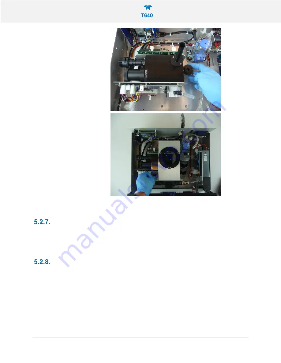
Page 75: ...obe back into the instrument CLEANING THE OPTICAL CHAMBER AND THE RH T SENSOR 1 Items needed Phillips Head screw driver 2 5mm Allen Wrench Canned Air cotton swabs and dry lint free non abrasive wipes 2 Remove the ASC support which straddles the sensors Make note of all connections electrical and plumbing that go between the components on the ASC support and the rest of the instrument Unplug the fl...

Page 76: ...08354B DCN7877 Teledyne API T640 PM Mass Monitor 74 3 Locate the optical cell nozzle the cup at bottom of optics chamber and its tubing and the Relative Humidity and Temperature RH T sensor ...

Page 77: ...08354B DCN7877 Teledyne API T640 PM Mass Monitor 75 4 Remove optical cell nozzle from optics chamber and remove cup including its tubing from optics chamber bottom detach RH T sensor tubing from the cup ...

Page 78: ...loth Figure 5 6 Maintenance Optics Chamber Windows 6 Use a can of compressed gas made specifically for electronics to blow any dust or other debris from the optics chamber from the cup from the bottom of the optics chamber and from the tubing Figure 5 7 Maintenance Final Dusting 7 Clean the optical cell nozzle using cotton swabs and canned air ...

Page 79: ...ASC support and the tubing from RH T sensor to the DFU filter o When re installing the ASC support the tubing from the optical cell cup to the DFU needs to be routed through the side above the diagonal support of the ASC support o Pay special attention not to place the support on top of any wires near the rear panel and CPU board The harness should be out of the way but it is a good idea to check ...

Page 80: ... can of compressed gas made specifically for electronics to blow through the line for final cleaning CHECKING FOR LEAKS The internal components of the T640 are not meant to be under strict vacuum as what would normally be done in a leak test So to avoid damage to internal components it is recommended that the inlet never be capped air tight while the instrument pump is running The Leak Check Zero ...

Page 81: ...uses and provides possible solutions Table 5 2 Alerts and Recommendations MESSAGE DESCRIPTION POSSIBLE SOLUTION S System Reset Warning raised when the system is reset Normal power cycle occurred If not check external power source Sample Flow Warning The Sample Flow is outside the set limits Check pneumatic fittings Re calibrate flow Bypass Flow Warning The Bypass Flow is outside the set limits Che...

Page 82: ... of range Check calibration make sure units match calibration device Replace pressure sensor Call Tech Support Time Sync Failure Unable to synchronize time with NTP server Check network and or internet connection Internal Serial Failure Internal serial communication error with sensor or control board Check connections and wires to board s Call Tech Support FLOW PROBLEMS If a flow auditing device i...

Page 83: ...particle level according to Lorenz Mie Theory Briefly the sampling head draws in ambient air with different sized particles which are dried with the Aerosol Sample Conditioner ASC and moved into the optical particle sensor where scattered light intensity is measured to determine particle size diameter The particles move separately into the T aperture through an optically differentiated measurement...

Page 84: ... the instrument This sensor analyzes the particles categorizing them by size and making the conversion to a mass concentration FLOW SENSOR AND PUMP CONTROL The T640 operates using ambient temperature and pressure compensated mass flow for accurate control of flow to actual volumetric conditions The flow stream is measured main flow at 5 LPM for T640 and bypass at 11 67 for 640X Option and a feedba...

Page 85: ...08354B DCN7877 Teledyne API T640 PM Mass Monitor 83 ELECTRONIC BLOCK DIAGRAM Figure 6 1 T640 with 640X Option Electronic Block Diagram ...

Page 86: ... 0 60 C Ambient Temp C 40 60 C LED Temp C 70 C Sample Temp C 0 60 C P3 Value 45 55 PMT HV Setting V 1100 2200V Pump PWM 80 640x Valve PWM 85 640x Option Bypass Flow LPM 11 67 5 640x Option Bypass Flow Slope 0 85 1 15 Used for diagnostics only and should not be set reset without explicit direction from TAPI Tech Support If P3 Calculated does not appear in the Dashboard configure the Dashboard Secti...

Page 87: ..._____________________________________________________________ __________________________________________________________________________________ __________________________________________________________________________________ __________________________________________________________________________________ __________________________________________________________________________________ ______...

Page 88: ...n Sample Flow Cal Bypass Flow Cal Pressure Cal PMT Adjust Leak Check Utilities Datalog View Alerts Log USB Utilities General DAS Download Setup Data Logging Events Dashboard Vars list of various features and functions with editable settings Homescreen Instrument Product Info System Info Network Settings Date Time Settings NTP Time Settings Language Remote Update Comm TCP Port1 TCP Port2 Network Se...

Reviews: