


MB1
User Manual
Page 23 of 37
7/6/12
Finally apply a light coating of silicone grease on the male ends of the Digibar cable and the connector on
the sonar, then connect the Digibar to the sonar using the short connector cable. Screw down the
connector collars finger tight.
4.3 Connecting
the
Sensors
The various cables to the RTA can be connected in any order, although the power to the RTA should only
be turned on when all the sensors are connected.
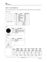
When each external sensor is configured (GPS, motion sensor etc.) the data format should be noted. At
a minimum this should be the type of data and the baud rate output from the sensor.
4.4
Powering Up and System Check
Once all of the required sensors have been connected, the system may be powered up. To power the
system, first ensure that the power cord is connected to the rear of the RTA, then depress the circular
power button on the face of the unit.
Once the power button is depressed, the lights will perform the following self check sequence:
(a) All lights in the IO box will flash once.
(b) The Link lights for both Sonar 1 and 2 will flash once.
(c) After 10 seconds, the Link lights for both Sonar 1 and 2 will flash once again.
(d) After 35 seconds, the link light for the sonar will begin to flash, and the system is ready for use.
4.5 Configuring
the
RTA
Each sensor input to the RTA is configured within the control software (Image) to ensure that the RTA
receives the data in the correct format, as noted in paragraph 4.2.2. Further information on using the
Image software can be found in the MB1 software manual.
4.6
Vessel Sensor Offsets
For precision hydrographic survey, the Cartesian coordinates of the offsets between each sensor should
be accurately measured and recorded for use in the data acquisition and/or post-processing software.
For this purpose, the acoustic center of the sonar is clearly marked on the sonar head by drilled marks on
the base of the unit, either side of the transmit array. For dimensions see Annex B.
If fitted, the internal motion sensor point of calculation is 121mm forward (y), 69.5mm up (z) and in line
with the centre (x = 0mm) of the acoustic center of the sonar. These values should be entered into the
acquisition software when the internal motion is used for motion compensation.
4.6
Assembling the Optional Fairing
An optional semi rigid fairing is available for the MB1 multibeam system. The fairing performs two
finctions. Primarily it is designed to reduce drag on the sonar when it is moving through the water.
Secondly it offers a limited amount of protection should the unit collide with an object in the water column
or the seafloor.
The fairing is assembled by performing the following actions:
Summary of Contents for MB1
Page 27: ...MB1 User Manual Page 27 of 37 7 6 12 Front section attached Complete Fairin ...
Page 29: ...MB1 User Manual Page 29 of 37 07 16 13 ANNEX B PHYSICAL DIMENSIONS ...
Page 30: ...MB1 User Manual Page 30 of 37 07 16 13 ...
Page 31: ...MB1 User Manual Page 31 of 37 7 6 12 ...