

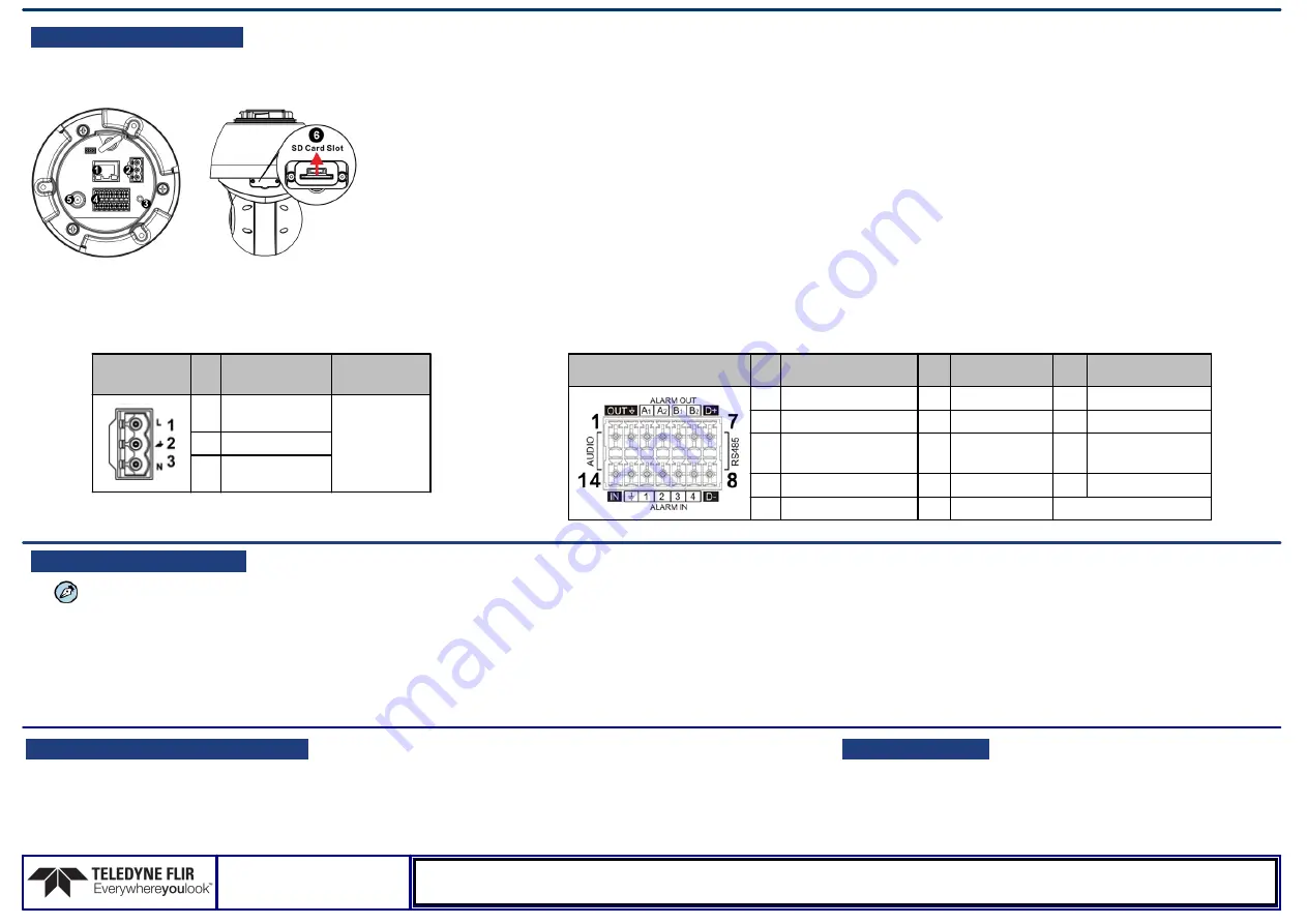
E. Connect the camera:
See connector references at left
1. Cat 5e/Cat 6 cable from the switch to the RJ45 connector for 10/100/1000
Mbps Ethernet and Universal PoE. If using a PoE injector, use CP-POE-4P-
60W-US or equivalent. Verify that there are steady green and flashing yellow
LEDs. If using a Universal PoE-capable network switch, use a Teledyne
FLIR-recommended unit. Consult Support.
2. Three-pin power connector (if using a 24VAC / 30 VDC power supply or a
heater).
3. Factory reset button. To reset factory defaults at any time, press the Default
button for at least 20 seconds.
4. 14-pin terminal block connector for alarm and audio in/out (attach wires from
external devices).
5. Analog video output to a DVR (attach coax cable to the BNC connector for
video output).
6. SD card slot (user-supplied microSDXC Class 10 card - up to 1TB).
CAUTION:
This product contains a battery that is soldered to
the PCB. There is a risk of explosion if the battery is
replaced by an incorrect type.
Do not replace the battery.
The battery should be disposed of in accordance
with manufacturer’s instructions.
3-Pin Power Connector
Power
Connector
Pin
24 VAC
30 VDC
1
L (Live; white;
positive)
Pins 1 and 3
(polarity N/A)
2
Ground (Earth)
3
N (Neutral;
black; negative)
Terminal Connectors
14-pin Terminal Block Pin
Definition
Pin
Definition
Pin
Definition
1 Audio-Out
6
Alarm-Out B2 11 Alarm-In2
2 Ground (Audio I/O)
7
RS-485 D+
12 Alarm-In 1
3 Alarm-Out A1
8
RS-485 D-
13 Ground (Alarm
I/O and RS-485)
4 Alarm-Out A2
9
Alarm-In 4
14 Audio-In
5 Alarm-Out B1
10 Alarm-In 3
G. Discover the Camera
1.
The camera’s web interface can be
accessed by Internet Explorer 10 and
higher (32-bit) with the ActiveX plug-in.
Set the Camera's IP address and Video Format
1. Download and install the DNA Utility from the FLIR website as
shown.
2. Attach the unit to the same LAN segment as the computer that
is managing the unit. DNA automatically discovers the unit on
the network and displays the device’s current IP address in the
Discover List.
3. Select the unit from the Discover List.
4. If using a Static IP address (as on a Latitude System), follow
the DNA instructions to set the desired IP address.
5. On a system using DHCP, select the DHCP option in DNA.
6. To select PAL or NTSC, select the device in the Discover List,
right-click to open the context menu, and click
Change Video
Format
.
7. Click
Update
.
H: If using Storage on the Edge
Use the Web interface to verify that the card status is displayed as Mounted on the
System > Edge Recording > SD
Card
screen.
1. Format the card.
2. Configure the camera to store snapshots and recordings from the
System > Edge Recording
screens.
I. Attach to VMS
Once you have completed installation and setup and found the
current IP address with DNA, use your VMS Discovery/Attach
procedures to attach the camera to your VMS.
CP-6302-31-I_QIG_v6
Teledyne FLIR LLC
Tel: +1-800-254-0632
6769 Hollister Ave.
Goleta, CA 93117
www.teledyneflir.com/security


