Automation
Section 4 The Column Selector Module
4-8
7. Place the columns into a clamp suitable for the column
size.
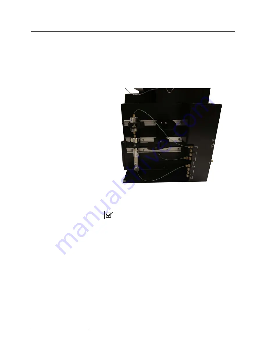
8. Using the provided tubing and a tubing cutter, connect the
column input port to the “T
O
C
OLUMN
” port on the Column
Selector Module. If a guard column is used, it can be
plumbed directly before the individual column.
9. Connect the column output port to the “F
ROM
C
OLUMN
”
port on the Column Selector Module.
Figure 4-14 Proper column connections on the Column
Selector Module
Note
Record of the position of the columns as you will need this
information during your initial configuration. After the configu-
ration is complete, the columns will be selected by name rather
than by how they are connected.
10. If desired, secure the housing of the Column Selector Mod-
ule back onto the module using the thumbscrews removed
in Step 1 of
Removing the housing from the EZ Prep
.
11. Connect the power supply from the Column Selector Mod-
ule to a power source.
4.1.3 Mounting the
AutoInjector Module to
the Column Selector
Module
The Column Selector Module can be used in conjunction with the
AutoInjector Module. Begin by installing the Column Selector
Module, and then install the AutoInjector Module using the steps
below:
1. Remove the cover plate from the top of the Column Selec-
tor Module by removing the two screws.
Summary of Contents for AutoInjector Module
Page 2: ......
Page 6: ...Automation Modules Installation and Operation Guide Safety Warnings 6 ...
Page 8: ...Automation Modules Table of Contents 8 ...
Page 10: ...Automation Modules Section 1 Introduction 1 2 ...
Page 46: ...Automation Section 3 The AutoSampler Module 3 24 ...
Page 64: ...Automation Section 4 The Column Selector Module 4 18 ...
Page 68: ...Automation Appendix A Specifications A 4 ...
Page 69: ...Compliance Statements C E D e c l a r a t i o n o f C o n f o r m i t y P e n d i n g ...
Page 70: ......
Page 72: ......
Page 74: ......


