


4 – Electrical Installation
4-2
© Teledyne TSS
DPN 402196 Issue 4.1
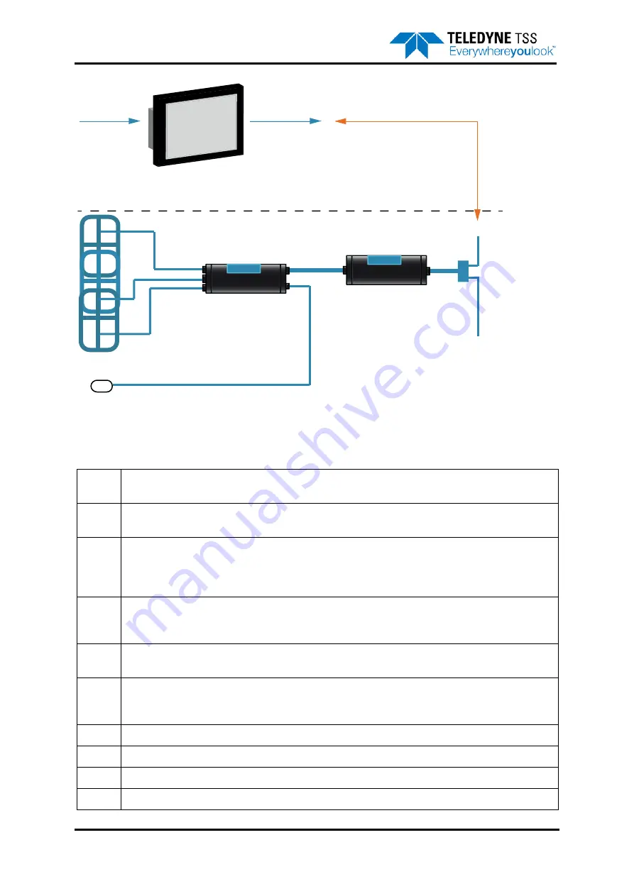
Figure 4-1: System interconnection diagram
Table 4-1: System interconnection details
A
The SDC accepts an AC electrical supply in the range 90 to 264VAC. The power demand is a maximum of
250VA.
B
Data communications from the SDC to the ROV umbilical. These can be 2-wire or 4-wire 20mA digital cur-
rent loop, or RS232. The default configuration is RS232 communication.
C
Power and communications cable (or ‘ROV Tail’) from the ROV to the PSU. This cable has cores to carry
the communication signals that pass between the SEP and the SDC, and power cores that supply mains
electrical power to operate the PSU. Refer to Table 4-2 "Power and Communications cable” beginning on
page 4-4 for details of the cable.
D
The PSU accepts AC power from the ROV electrical distribution system through the ROV tail.
The maximum current drawn from the supply is approximately 2.8A (at 100V to 120V). As an option, Tele-
dyne TSS can supply a PSU that accepts AC power at 230V instead.
E
Connection between the PSU and the SEP is through a single cable. The cable has a 12-way connector
that connects to the SEP.
F
The SEP accepts power from the PSU and communicates with the SDC through the PSU to SEP cable. The
SEP provides power to, and communicates with the sub-sea altimeter through the sub-sea altimeter cable.
The SEP drives the search coils through the coil search cables.
G
Three coil connection cables
H
Three Teledyne TSS search coils arranged as shown with connections to Channels 1 to 3 on the SEP.
I
Power and data cable that connects the altimeter to the SEP
J
Sub-sea altimeter
AC Input
Power
Supply
A
A
B
Electrical
Supply
C
D
E
F
G
H
I
J
Communications
ROV umbilical (user supplied)
Summary of Contents for 440
Page 12: ...List of Figures x Teledyne TSS DPN 402196 Issue 4 1 ...
Page 18: ...Glossary xvi Teledyne TSS DPN 402196 Issue 4 1 ...
Page 24: ...1 Introduction 1 6 Teledyne TSS DPN 402196 Issue 4 1 ...
Page 32: ...2 System Overview 2 8 Teledyne TSS DPN 402196 Issue 4 1 ...
Page 66: ...4 Electrical Installation 4 20 Teledyne TSS DPN 402196 Issue 4 1 ...
Page 88: ...5 Operating Software 5 22 Teledyne TSS DPN 402196 Issue 4 1 Figure 5 10 Altimeter Test ...
Page 144: ...6 Operating Procedure 6 40 Teledyne TSS DPN 402196 Issue 4 1 ...
Page 154: ...7 Operational Considerations 7 10 Teledyne TSS DPN 402196 Issue 4 1 ...
Page 164: ...8 System Specifications 8 10 Teledyne TSS DPN 402196 Issue 4 1 ...
Page 203: ...10 System Drawings DPN 402196 Issue 4 1 Teledyne TSS 10 17 Figure 10 15 SDC10 Dimensions ...
Page 230: ...A Operating Theory A 12 Teledyne TSS DPN 402196 Issue 4 1 ...
Page 242: ...B Options B 12 Teledyne TSS DPN 402196 Issue 4 1 ...
Page 244: ...C Altimeter C 2 Teledyne TSS DPN 402196 Issue 4 1 ...
Page 246: ...D Reference D 2 Teledyne TSS DPN 402196 Issue 4 1 ...
Page 248: ...D Reference D 4 Teledyne TSS DPN 402196 Issue 4 1 ...
Page 250: ...D Reference D 6 Teledyne TSS DPN 402196 Issue 4 1 ...
Page 252: ...D Reference D 8 Teledyne TSS DPN 402196 Issue 4 1 ...
Page 254: ...D Reference D 10 Teledyne TSS DPN 402196 Issue 4 1 ...