Clock Configuration and Other Switch Settings
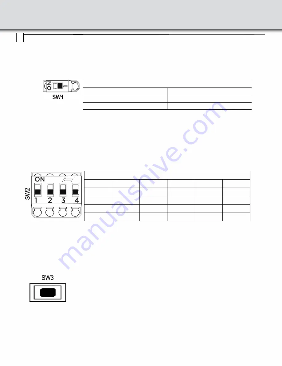
SW1: DUT Power LED Status
This switch connects the DUT power indication LEDs to the bus power. SW1 is located on the front of the interposer near
the retention clamp and is configurable according to table below:
SW2: Clock Source Control
The source for the reference clock used by the analyzer to record PCI Express traffic is configurable according to below
table for SW2. Make sure clock source in Recording Options in the PCIe Protocol Analysis application is set to External.
Note:
Factory settings for all switches are ON.
SW3: Active Width Control Pushbutton
Pushbutton SW3 allows the user to change the link width enabled on the interposer by pressing SW3 multiple times.
SW1: DUT Power LED Status on Interposer
Selection SW1
LED Connected (Default)
ON
LED Disconnected
OFF
SW2: CONFIG-ANALYZER REFCLK SEL
Port B
1
2
Port A
3
4
REFCLK
ON
ON
REFCLK
ON
ON
US_CLK_IN
OFF
ON
US_CLK_IN
OFF
ON
DS_CLK_IN
ON
OFF
DS_CLK_IN
ON
OFF
N/A
OFF
OFF
N/A
OFF
OFF
Pushbutton SW3 is used to turn off the terminations and remove all loads on the unused interposer
receivers depending on the maximum number of lanes to be analyzed. Press the pushbutton switch
(SW3) to move to the next active width as indicated by the LEDs (next to the switch) on the interposer.
This is useful for devices that require terminations not to be present in order to train to a lower link width.
Note:
Even though the Active Width may be lower than x16, it may be possible that the Signal Detect
LEDs for higher lanes are ON if those lanes are transmitting signal.
5
Note:
This switch connects the DUT power indication LEDs to the bus power. In some
systems with Hot-Plug management the Power Indication LEDs on the interposer may
prevent the host system from turning ON bus power to the device, if this happens
disconnect the LEDs using SW7 to allow proper bus power operation.


