background image


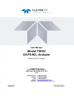
User Manual


Model T500U 

CAPS NO

2

 Analyzer 

with NumaView™ software 


© TELEDYNE API (TAPI) 

9970 CARROLL CANYON ROAD  

SAN DIEGO, CALIFORNIA 92131-1106 

USA


Toll-free Phone:  +1 800-324-5190 

Phone:  +1 858-657-9800 

Fax:  +1 858-657-9816 

Email: 

[email protected]


Website: 

http://www.teledyne-api.com/ 


Copyright 2019 

083730510A DCN8172 

Teledyne API 

05 September 2019 

Summary of Contents for T500U

Page 1: ...NE API TAPI 9970 CARROLL CANYON ROAD SAN DIEGO CALIFORNIA 92131 1106 USA Toll free Phone 1 800 324 5190 Phone 1 858 657 9800 Fax 1 858 657 9816 Email api sales teledyne com Website http www teledyne a...

Page 2: ......

Page 3: ...ftware i NOTICE OF COPYRIGHT 2019 Teledyne API TAPI All rights reserved TRADEMARKS All trademarks registered trademarks brand names or product names appearing in this document are the property of thei...

Page 4: ...thout protection or proper tools could result in damage to the part s and or the instrument Technician Symbol All operations marked with this symbol are to be performed by qualified maintenance person...

Page 5: ...renseignements sp cifiques MISE EN GARDE Surface chaude Ne pas toucher Toucher certaines parties de l instrument sans protection ou sans les outils appropri s pourrait entra ner des dommages aux pi c...

Page 6: ...NT Equipment provided but not manufactured by TAPI is warranted and will be repaired to the extent and according to the current terms and conditions of the respective equipment manufacturer s warranty...

Page 7: ...his manual in its entirety before operating the instrument CONVENTIONS USED In addition to the safety symbols as presented in the Safety Messages page this manual provides special notices related to t...

Page 8: ...puts 23 Connecting the Control Inputs Digital Inputs 24 Concentration Alarm Relay Option 61 25 Connecting Communications Interfaces 25 Pneumatic Connections 30 Critical Tubing Pressure Venting and Exh...

Page 9: ...Hessen Com Port Configuration 70 Hessen Settings Configuration 71 Hessen Gas List 72 4 CALIBRATION 73 Important Precalibration Information 73 Calibration Requirements 73 Zero Air 74 Calibration Span G...

Page 10: ...e Concentrations 99 Absence of Analyzer Response to Sample Gas 99 Unstable Zero and Span 99 Inability to Span Deactivated SPAN Button 100 Inability to Zero Deactivated ZERO Button 100 Non Linear Respo...

Page 11: ...lerts Cleared 44 Figure 2 25 Utilities Alerts Log of Active and Past Alerts and Events 44 Figure 2 26 Datalog Configuration New Log Page 46 Figure 2 27 Datalog Configuration Existing Log 46 Figure 2 2...

Page 12: ...nts 24 Table 2 5 Control Input Pin Assignments 25 Table 2 6 Menu Overview 39 Table 2 7 Utilities Submenu Descriptions 45 Table 2 8 List of Variables with Descriptions 54 Table 2 9 Analog Output Voltag...

Page 13: ...tends the time or life of the photon thus providing ample time to measure absorbance when NO2 is present Through the use of precisely timed data acquisition coupled with a proprietary algorithm the me...

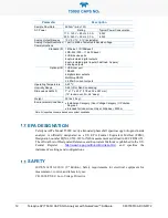
Page 14: ...ensions HxWxD 7 x 17 x 23 5 178 x 432 x 597 mm 19 rack mount 5U 24 deep Weight 33 lbs 15 kg Environmental Conditions Installation Category Over Voltage Category II Pollution Degree 2 Intended for Indo...

Page 15: ...umaView Software 13 EMC IEC EN 61326 1 Class A Emissions Industrial Immunity FCC 47 CFR Part 15B Class A Emissions CE 2004 108 EC Electromagnetic Compatibility Directive OTHER CERTIFICATIONS EU EN1421...

Page 16: ...website at http www teledyne api com ATTENTION COULD DAMAGE INSTRUMENT AND VOID WARRANTY Do not operate this instrument without first removing dust plugs from SAMPLE and EXHAUST ports on the rear pane...

Page 17: ...ents are intact and securely seated 3 Check the connectors of the various internal wiring harnesses and pneumatic hoses to ensure they are firmly and securely seated 4 Verify that all of the optional...

Page 18: ...anel rear panel connectors and the internal chassis layout FRONT PANEL The front panel Figure 2 1 includes two USB ports for peripheral device connections which can be used with mouse and keyboard as...

Page 19: ...083730510A DCN8172 Teledyne API T500U CAPS NO2 Analyzer with NumaView Software 17 REAR PANEL Figure 2 2 shows the layout of the rear panel Figure 2 2 Rear Panel Layout...

Page 20: ...t a gas line to the source of calibrated span gas here ZERO AIR On units with zero span valve option installed attach a gas line to the source of zero air here If a permeation oven also known as inter...

Page 21: ...083730510A DCN8172 Teledyne API T500U CAPS NO2 Analyzer with NumaView Software 19 INTERNAL CHASSIS Figure 2 3 shows the internal chassis layout Figure 2 3 Internal Chassis Layout...

Page 22: ...e Power connection must have functioning ground connection Do not defeat the ground wire on power plug Turn off instrument power before disconnecting or connecting electrical subassemblies Do not oper...

Page 23: ...3 is available for A1 A2 and A3 only To access these signals attach a strip chart recorder and or data logger to the appropriate analog output connections on the rear panel of the analyzer Configure...

Page 24: ...or 4 20 mA also have a 5 under range Figure 2 5 provides installation instructions and illustrates a sample configuration of one current output combined with two voltage outputs Next are instructions...

Page 25: ...tput CONNECTING THE STATUS OUTPUTS DIGITAL OUTPUTS The 12 pin STATUS connector allows the digital status outputs to report analyzer conditions configured through the Setup Digital Outputs menu via opt...

Page 26: ...on should be used as the ground return when 5VDC power is used CONNECTING THE CONTROL INPUTS DIGITAL INPUTS With zero and span valves option installed two digital control inputs in the rear panel CONT...

Page 27: ...00 mA combined with the analog output supply if used CONCENTRATION ALARM RELAY OPTION 61 The concentration relay option provides four 4 dry contact relays on the rear panel Figure 2 8 each with 3 pins...

Page 28: ...PI part number WR000077 or a DB9 female to DB25 male cable Option 60A as applicable from the analyzer s RS 232 port see Figure 2 9 for connector pin assignments to the device Adjust the rear panel DCE...

Page 29: ...h wiring and should require no additional adapters To assist in properly connecting the serial ports to either a computer or a modem there are activity indicators just above the RS 232 port Once a cab...

Page 30: ...enting ESD damage refer to the manual Fundamentals of ESD PN 04786 which can be downloaded from our website at http www teledyne api com under Help Center Product Manuals in the Special Manuals sectio...

Page 31: ...male DB9 female cables to interconnect the host RS232 port to the first analyzer s RS232 port then from the first analyzer s COM2 port to the second analyzer s RS232 port from the second analyzer s C...

Page 32: ...d press the Enter button 8 Next in the Setup Comm COM1 menu do not use the COM2 menu for multidrop use the Edit button to set COM1 Quiet Mode and COM1 Multidrop to ENABLED then press the Accept button...

Page 33: ...operation ATTENTION COULD DAMAGE INSTRUMENT AND VOID WARRANTY VENT PRESSURIZED GAS When any gas span zero air sample is received from a pressurized manifold always provide a vent to equalize the pres...

Page 34: ...h 2 meters to 10 meters Pressure All Sample gas pressure must be at ambient atmospheric pressure no greater than 1 0 psig Venting to prevent back diffusion and pressure effects Run tubing outside the...

Page 35: ...asic Configuration For the analyzer s basic configuration in addition to tubing pressure venting and exhaust requirements set out in Section 2 3 2 1 attach the following pneumatic lines SAMPLE GAS SOU...

Page 36: ...EUMATIC FLOW DIAGRAMS This section shows a diagram of the basic pneumatic flow with the zero span valves option Figure 2 14 and with the internal zero span Option Figure 2 15 PNEUMATIC FLOW FOR BASIC...

Page 37: ...UP FUNCTIONAL CHECKS AND CALIBRATION We recommend reading Section 6 to become familiar with the principles of operation When the instrument is first started Section 2 3 4 1 check its functionality Sec...

Page 38: ...Upon initial startup a sequence of status screens Figure 2 16 appear prior to the Home page Figure 2 17 Figure 2 16 Status Screens at Startup Upon any startup this instrument should warm up for appro...

Page 39: ...r configured Events Section 2 4 3 provides more detailed information about Alerts and Section 2 5 2 addresses Events Alerts can be viewed and cleared via either the Alerts menu or the Alerts shortcut...

Page 40: ...configure the Dashboard through the Setup Dashboard menu to add them see Section 2 4 2 These functions are also useful tools for diagnosing problems information provided in Section 5 7 2 Figure 2 19...

Page 41: ...ts Section 2 5 2 and create customized triggers for data logging functions Section 2 5 1 Events Select parameters and define the conditions by which they are to be flagged and recorded in the Alerts l...

Page 42: ...Figure 2 20 presents an orientation to the main display screen Figure 2 21 shows that pressing the gas name or its concentration value or a meter below displays a live plot of their respective readin...

Page 43: ...083730510A DCN8172 Teledyne API T500U CAPS NO2 Analyzer with NumaView Software 41 Figure 2 21 Concentration and Stability Graph top and Meter Graph bottom...

Page 44: ...shboard displays an array of user selectable parameters and their values Section 2 5 3 provides configuration instructions If there is a graphing icon in the upper right corner of a parameter pressing...

Page 45: ...any other page View a list of currently active Alerts by pressing either the Alerts menu on the Home screen or by pressing the Alerts shortcut Figure 2 23 While Alerts can be cleared from the Active A...

Page 46: ...ts can reappear if the conditions causing them are not resolved For troubleshooting guidance refer to Section 0 Figure 2 24 Active Alerts Cleared Alerts and Events remain recorded in the Utilities Ale...

Page 47: ...isition system DAS by configuring the Data Logger in the Setup Data Logging menu Section 2 5 1 Analog Outputs Show the voltage signals for the functions selected and configured in the Setup Analog Out...

Page 48: ...me model Section 2 6 SETUP DATA LOGGING DATA ACQUISITION SYSTEM DAS The Datalogger can be configured to capture and store user defined data which then can be viewed in the Alerts page if elected as we...

Page 49: ...Teledyne API T500U CAPS NO2 Analyzer with NumaView Software 47 Figure 2 28 Creating a New Data Log The parameters available in the list of Log Tags include the names of Events configured in the Events...

Page 50: ...RIGGER TYPES PERIODIC The Periodic trigger is a timer based trigger that is used to log data at a specific time interval Periodic Trigger requires an interval that is set to number of minutes and a st...

Page 51: ...ta collected by the Datalogger from the instrument to a flash drive navigate to the Utilities USB Utilities DAS Download menu 1 Insert a flash drive into a front panel USB port and wait for the Status...

Page 52: ...nformation on instrument functionality such as concentration alarms Some Events are standard and not editable while others are user configurable described here Existing Events are listed in the Events...

Page 53: ...age when it is triggered it will still be recorded and can be viewed in the Utilities Alerts Log To use this option the Event must be enabled allows the choice of whether or not to keep an Event visib...

Page 54: ...0510A DCN8172 Figure 2 34 Configured Event Sample EDITING OR DELETING EVENTS Select an Event from the list Figure 2 32 and press the Edit button to view or edit the details Figure 2 34 or press the De...

Page 55: ...s for data logging functions The name entered in the Name field of the Events Configuration page will appear in the list of Log Tags of the Datalog Configuration page The Data Logger is presented in S...

Page 56: ...nel display and reported via the instrument s various outputs 1 Set the appropriate units of measure Setup Vars User Units 2 Select the reporting range mode Setup Vars Range Mode and set the reporting...

Page 57: ...each of the three meters at the bottom of the Home page navigate to the Homescreen configuration page through either the Setup Homescreen menu or from Home page using the configuration icon Figure 2 3...

Page 58: ...l relays can also be mapped To map Digital Outputs to Signals select a pin in the Outputs list then make a selection from the Signals list and press the Map button if as needed change the polarity by...

Page 59: ...gnal Calibration Type AUTO for group calibration Figure 2 40 of the analog outputs cannot be selected when Current is selected for the Range MANUAL for individual calibration Figure 2 41 of analog out...

Page 60: ...n adjustments see Section 2 5 8 1 for voltage and Section 2 5 8 2 for current RANGE1 RANGE SPAN MINIMUM OUTPUT MAXIMUM OUTPUT 100mV 0 100 mVDC 5 mVDC 105 mVDC 1V 0 1 VDC 0 05 VDC 1 05 VDC 5V 0 5 VDC 0...

Page 61: ...djust field of the Analog Outputs Calibration screen Figure 2 41 Refer to Table 2 10 for voltage tolerances V DC Gnd Recording Device V IN V IN ANALYZER V OUT V OUT Volt Meter Figure 2 42 Setup for Ch...

Page 62: ...ce the exact amount by which the current signal is changed per D to A count varies from output to output and instrument to instrument you will need to measure the change in the signal levels with a se...

Page 63: ...u MENU DESCRIPTION Product Info View Model Part and Serial Numbers and Package and Driver Versions and options information System Info View Windows and RAM information Network Settings View the networ...

Page 64: ...for that COM port Modem Connection Select either a modem connection or a direct cable connection Modem Init String Input an initialization string to enable the modem to communicate Multidrop Enable di...

Page 65: ...P PORT2 TCP Port2 is configured with the port number for MODBUS TCP PORT3 TCP Port3 is configured with the port number for Hessen NETWORK SETTINGS The Setup Comm Network Settings menu is for Ethernet...

Page 66: ...an IP address and divides the IP address into network address and host address and identifies the LAN to which the device is connected All addressable devices and computers on a LAN must have the sam...

Page 67: ...ome Utilities USB Utilities General page 2 Insert a flash drive into either of the two front panel USB ports 3 When the Status field indicates that the USB drive has been detected press the Download C...

Page 68: ...cation equipment DCE Basic terminals always fall into the DTE category whereas modems are always considered DCE devices The difference between the two is the pin assignment of the Data Receive and Dat...

Page 69: ...al for more information on CAS systems SERIAL COMMUNICATION RS 485 OPTION The COM2 port of the instrument s rear panel is set up for RS 232 communication but can be reconfigured for RS 485 communicati...

Page 70: ...and possibly a null modem adapter or cable MODBUS COM PORT CONFIGURATION MODBUS communications can be configured for transmission over Ethernet or serial COM port through the Setup Comm menu Make the...

Page 71: ...it to Software Press the Accept button to apply the settings Figure 3 2 shows an example for MODBUS RTU Figure 3 2 MODBUS via Serial Communication example Important When more than one analyzer is conn...

Page 72: ...hile Teledyne API s application is completely compatible with the protocol itself it may be different from implementations by other companies HESSEN COM PORT CONFIGURATION Configure the COM1 COM2 port...

Page 73: ...nt are encoded as the traditional command format Style and format of responses depend on exact coding of the initiating command BCC Responses from the instrument are always delimited with STX at the b...

Page 74: ...EN TEMP WARNING x80 1000 0000 UNASSIGNED FLAGS MANIFOLD TEMPERATURE2 FRONT PANEL COMMUNICATION WARNING BOX TEMP WARNING ANALOG CALIBRATION WARNING SYSTEM RESET DYNAMIC ZERO WARNING RELAY BOARD WARNING...

Page 75: ...on with EPA protocols IMPORTANT PRECALIBRATION INFORMATION Note A start up period of 4 5 hours is recommended prior to calibrating the analyzer CALIBRATION REQUIREMENTS The following equipment supplie...

Page 76: ...d using an NO2 gas of higher concentration combined with a gas dilution calibrator such as the Teledyne API Model T700 Calibrators mix high concentration gas with zero air to accurately produce span g...

Page 77: ...recorder data acquisition system or digital data acquisition system should be used to record data from either the Ethernet serial or analog outputs If analog readings are used the response of the reco...

Page 78: ...configuration instruments see Section 4 2 1 To calibrate or to perform a calibration check for instruments with valve options see Section 4 2 2 To perform a calibration check for instruments with the...

Page 79: ...libration M P menu input NO Span gas through the Sample port and press the Start button 2 Either check or calibrate as follows CHECK ONLY ACTUAL CALIBRATION a Wait to reach stability then press Stop b...

Page 80: ...ACT CLOSURE Contact closures for controlling calibration and calibration checks are located on the rear panel CONTROL IN connector Instructions for setup and use of these contacts are in Section 2 3 1...

Page 81: ...leaving the instrument s internal calibration variables unchanged AUTOMATIC ZERO SPAN CAL CHECK AUTO CAL The Auto Cal feature allows unattended periodic operation of the ZERO SPAN valve options by us...

Page 82: ...o causes a Low Span check when the Enabled box is also and the Calibrate box is unchecked disables Low Span calibration and check High causes the sequence to perform a High Span concentration calibrat...

Page 83: ...or more sequences at the same time of the day Any new sequence that is initiated whether from a timer the COM ports or the contact closure inputs will override any sequence that is in progress It is...

Page 84: ...ilt in warning features periodic inspection regular zero span checks regular test parameter evaluation for predictive diagnostics and data analysis and routine maintenance Any instrument s supplying t...

Page 85: ...d In certain environments e g dusty very high ambient pollutant levels some maintenance procedures may need to be performed more often than shown WARNING ELECTRICAL SHOCK HAZARD Disconnect power befor...

Page 86: ...s Annually or after repairs involving pneumatics Yes if a leak is repaired Internal Pump Replace Measured Flow less than 800 cm3 min Yes PREDICTIVE DIAGNOSTICS Predictive diagnostic functions includin...

Page 87: ...ebris on mirrors Replace charcoal scrubber NO2 Conc Concentration Constant for constant concentration Decreasing over time Developing leak in pneumatic system Check for leaks OPERATIONAL HEALTH CHECKS...

Page 88: ...If an update is available it can be downloaded through this page Figure 5 2 Remote Update Page MANUAL RELOAD UPDATE PROCEDURES To reload or update firmware first contact Technical Support to obtain t...

Page 89: ...l button will be enabled if the firmware version on the flash drive is the same as or older than the current firmware of the instrument the Install button will not be enabled 5 Press the Install butto...

Page 90: ...rify return to Home page then back to the Date Time Settings page and check that the selected Time Zone is now highlighted 4 Without making any other changes power OFF the instrument and power ON agai...

Page 91: ...lter REPLACING THE AREF FILTER AND CHARCOAL FILTER The AREF filter assembly consists of the AREF filter which is a backup particulate filter and the charcoal filter which is an NO2 gas scrubber 1 Turn...

Page 92: ...ubes from the hose barb connections on the pump 5 Remove the four screws that hold the pump bracket assembly to the bottom of the chassis 6 Disconnect the power connector labeled pump located about 4...

Page 93: ...trument will not be operated for several or more hours Ensure that the tube is placed into the larger of two holes and that the open permeation end of the tube plastic is facing up 6 Re attach the cov...

Page 94: ...rear panel 3 Cap rear panel ports and cap the pump port If zero span valves are installed disconnect the tubing from the zero and span gas ports and cap the ports Figure 2 2 4 Pressurize the instrume...

Page 95: ...he tubing then check for leaks 5 Once kinks and leaks are ruled out first replace the sample flow restrictor and if the sample flow is still out of specification replace the sample filter 6 If flow is...

Page 96: ...that the analyzer s DC power wiring is color coded and these colors match the color of the corresponding test points on the relay PCA 4 Suspect a leak first Customer service data indicate that the ma...

Page 97: ...ased Failed Disk on Module User erased data DATA INITIALIZED Data Storage in DAS was erased before the last power up occurred Failed Disk on Module User cleared data REAR BOARD NOT DET Motherboard not...

Page 98: ...t gain in altitude A variety of factors such as air conditioning systems passing storms and air temperature can also cause changes in the absolute atmospheric pressure Table 5 4 Dashboard Functions In...

Page 99: ...determining if the analyzer s CPU I2 C bus and Relay PCA are functioning properly CPU STATUS INDICATOR DS5 a red LED located on the motherboard Figure 5 8 flashes when the CPU is running the main pro...

Page 100: ...hdog and Status LED Failure Indications LED COLOR FUNCTION INDICATED FAILURE S D1 Red I2C bus Health Watchdog Circuit Failed Halted CPU Faulty Motherboard Touchscreen or Relay PCA Faulty Connectors Wi...

Page 101: ...O SAMPLE GAS If the instrument shows no response display value is near zero even though sample gas is supplied properly and the instrument seems to perform correctly 1 Confirm the lack of response by...

Page 102: ...One possible indicator of this scenario is a slope or offset value that is outside of its allowed range 0 8 1 2 for slope 10 to 10 for offsets INABILITY TO ZERO DEACTIVATED ZERO BUTTON In general the...

Page 103: ...og outputs running at 0 1 V full scale should always be calibrated manually See Section 2 5 8 1 for a detailed description of this procedure OTHER PERFORMANCE PROBLEMS Dynamic problems i e problems th...

Page 104: ...hat the Auto Reference valve is operating properly To do so use the Utilities Diagnostics Digital Outputs menu to toggle the valve on and off Listen to hear whether the valve is switching and see if t...

Page 105: ...g and will restart after the sample pressure reaches an acceptable level If the configuration plug is set for 115 or 100 VAC and the unit is plugged into a 230 VAC circuit the circuit breaker built in...

Page 106: ...DGND 1 0 05 0 05 PS1 Chassis DGND 1 Chassis N A 0 05 0 05 PS2 12 12V Ret 6 12V 7 11 8 12 5 PS2 DGND 12V Ret 6 DGND 1 0 05 0 05 I2C BUS Verify operation of the I2 C bus by checking whether the LEDs ar...

Page 107: ...then the associated control device on the Relay PCA is bad DATA ACQUISITION DAQ PCA If the warning message BENCH COM WARNING appears on the front panel display check that the serial cable between the...

Page 108: ...oltage at its origin see the interconnect drawing in Appendix B with the voltage displayed through the signal I O function If the wiring is intact but there is a large difference between the measured...

Page 109: ...lashing In some rare circumstances this failure may be caused by a bad IC on the motherboard specifically U57 the large 44 pin device on the lower right hand side of the board If this is true removing...

Page 110: ...cted by humidity Variations in humidity between day and night are usually enough to yield very variable output results If the instrument is installed in an air conditioned shelter the air is usually d...

Page 111: ...INSTRUMENT AND VOID WARRANTY Servicing of circuit components requires electrostatic discharge protection i e ESD grounding straps mats and containers Failure to use ESD protection when working with e...

Page 112: ...7 It may be necessary to straighten the pins somewhat to fit them into the socket Press the chip all the way in 8 Close the rear panel and turn on power to the machine 9 If the replacement DOM carrie...

Page 113: ...ecalibration of the analyzer to an out of range response curve EXAMPLE The span set point is 400 ppb but gas concentration being measured is only 50 ppb How do I enter or change the value of my Span G...

Page 114: ...tion 2 3 1 7 under RS 232 Connection The DCE DTE switch on the back of the analyzer is not set properly ensure that both green and red lights are on Section 3 1 The baud rate of the analyzer s COM por...

Page 115: ...cal optical cell Figure 6 1 through the rear of mirror A The intensity of the light as observed by the detector which is also modulating at a slightly different frequency located behind Mirror B build...

Page 116: ...specificity SAMP PRESS SAMP TEMP T500U OVEN DETECTOR LED 2X LENS BANDPASS FILTER 2X 450 nm MIRRORS Sample In Sample Out Mirror A Mirror B Figure 6 1 T500U Optical Absorption Cell Figure 6 2 Phase Shif...

Page 117: ...ane H2O water vapor HC general abbreviation for hydrocarbon HNO3 nitric acid H2S hydrogen sulfide NO nitric oxide NO2 nitrogen dioxide NOX nitrogen oxides here defined as the sum of NO and NO2 NOy nit...

Page 118: ...Protocol IZS Internal Zero Span LAN Local Area Network LCD Liquid Crystal Display LED Light Emitting Diode LPM Liters Per Minute MFC Mass Flow Controller M R Measure Reference NDIR Non Dispersive Inf...

Page 119: ...a maximum cable length of 50 feet RS 485 specification and standard describing a binary serial communication method among multiple devices at a data rate faster than RS 232 with a much longer distanc...

Page 120: ...emperature duty cycle 30 5 Manifold temperature C 32 5 Manifold temperature duty cycle 34 6 IZS lamp temperature C 36 6 IZS temperature duty cycle 38 Sample temperature C 40 Sample pressure Inches Hg...

Page 121: ...ut 8 slope eng unit V 176 10 External analog input 8 offset eng unit MODBUS Floating Point Holding Registers 32 bit IEEE 754 format read write in high word low word order read write 2 Maps to NO2_SPAN...

Page 122: ...tput signal 37 MB_RELAY_37 in signal I O list 2 Maps to relay output signal 38 MB_RELAY_38 in signal I O list 3 Maps to relay output signal 39 MB_RELAY_39 in signal I O list 20 1 Triggers zero calibra...

Page 123: ...ce 06697 J2 J1 07215 J9 J15 12 5 15 J14 AZ Valve Sample Valve J1 J4 J3 J8 SK1 SK1 SK2 SK2 045230100 SWITCH AC POWER ENTRANCE AC POWER RELAY BOARD PS2 PS1 J11 CN3 CN5 CN4 J1 Xmitter 06881 W MD 06950 J3...

Reviews: