background image

Signal Inputs and Outputs

SDI Signals

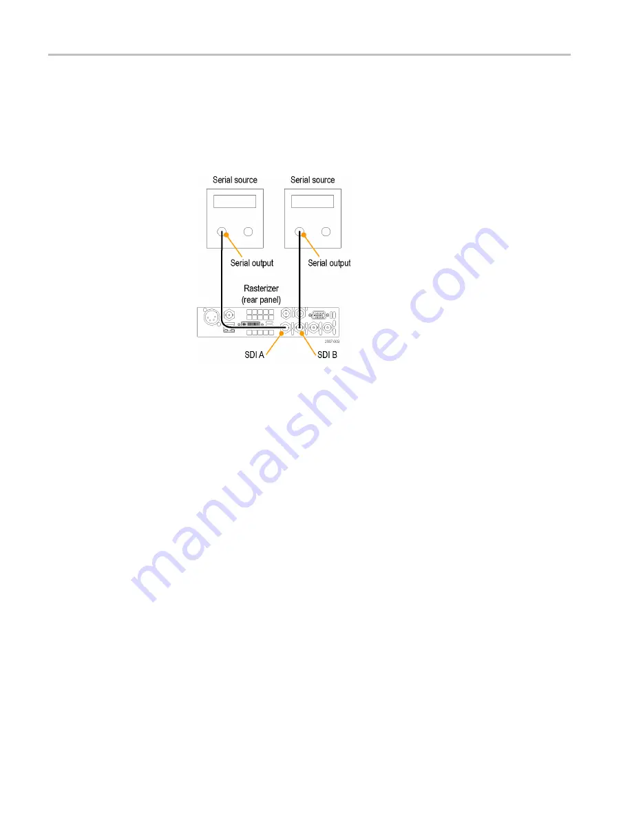
Connect one or more 3G-SDI, HD-SDI, or SD-SDI signals to the SDI inputs
on the rear panel of the instrument. After that is

fi

nished, use the front panel

buttons to set the parameters for monitoring the signals, such as thresholds, alarms
monitored, and audio source. (See Figure 6.)

Figure 6: Two SDI signal connection

Dual Link Signals

The inputs for dual link signals are the same as for SDI signals. Dual Link
monitoring allows you to set up your instrument to monitor higher resolution
signals than can be monitored using the traditional single link input. Dual link
signals are combined in the instrument and then shown as a single signal on
a waveform or other display.

When you set input formats, sample structure, and transport type to Auto in the

CONFIG > SDI Input

menu, your instrument automatically con

fi

gures for

Dual Link signals if SMPTE352M (VPID) is present. If SMPTE352M (VPID)
is not present, you must manually set up sample structure and transport. View
the Video Session Display (

STATUS>Display Type>Video Session

) to verify

proper con

fi

guration.

Your instrument automatically detects the format on signals with SMPTE352M
(VPID) while operating on Dual Link signals. You can then view combined Link
A, Link B, and Alpha Channel information, which can help with the identi

fi

cation

of correct content. Alpha Channel information is visible, if present. The following
illustration is an example of how the signal components would appear. (See
Figure 7.)

20

WVR5200 Waveform Rasterizer User Manual

Summary of Contents for WVR5200 Series

Page 1: ...xx WVR5200 Waveform Rasterizer ZZZ User Manual P077053203 077 0532 03...

Page 2: ......

Page 3: ...WVR5200 Waveform Rasterizer ZZZ User Manual xx www tektronix com 077 0532 03...

Page 4: ...n this publication supersedes that in all previously published material Specifications and price change privileges reserved TEKTRONIX and TEK are registered trademarks of Tektronix Inc TandemVu is a r...

Page 5: ...taxes and any other charges for products returned to any other locations This warranty shall not apply to any defect failure or damage caused by improper use or improper or inadequate maintenance and...

Page 6: ......

Page 7: ...and Outputs 19 SDI Signals 20 Dual Link Signals 20 Reference Loop 21 Signal Generation 22 Display Information 23 Multi Input Display Mode 25 Simultaneous Input Monitoring 28 3D Input Monitoring 29 Syn...

Page 8: ...ARIB STD B 37 Display and Status Screens 108 ARIB STD B 35 Display and Status Screens 111 ARIB TR B 23 1 Display and Status Screens 113 ARIB TR B 23 2 Display and Status Screens 115 ARIB TR B 22 Disp...

Page 9: ...Figure 15 3D Left and Right Eye images showing Disparity Grid and Disparity Cursor measurement using SIM 33 Figure 16 Vector display with Luma Qualified Vector LQV enabled 36 Figure 17 Lightning disp...

Page 10: ...Figure 49 ARIB Status display showing no data present 104 Figure 50 ARIB STD B 39 display with the associated ARIB Status display 105 Figure 51 ARIB STD B 37 display with the associated ARIB Status di...

Page 11: ...Table of Contents List of Tables Table i Product documentation ix Table 1 Service options 4 WVR5200 Waveform Rasterizer User Manual v...

Page 12: ...manual for further ratings information before making connections to the product Do not apply a potential to any terminal including the common terminal that exceeds the maximum rating of that terminal...

Page 13: ...could result in damage to this product or other property Symbols and terms on the product These terms may appear on the product DANGER indicates an injury hazard immediately accessible as you read th...

Page 14: ...General safety summary viii WVR5200 Waveform Rasterizer User Manual...

Page 15: ...you can find this and more information about your product You can always find the most updated documentation and software for your product on the Tektronix Web site at www tektronix com downloads Tab...

Page 16: ...nformation about installing the instrument into a system Available on the Product Documentation CD and the Web at www tektronix com downloads SNMP commands 077 0261 XX WFM and WVR Series Management In...

Page 17: ...h rasterizer that provides comprehensive video and embedded audio features across 3 Gb s SD and HD signal formats This instrument provides an ideal solution for basic video and audio with Option AUD m...

Page 18: ...ed vector display Option PROD Vector display that is gated by a specified luminance range Each vector tile may have a different luminance range specified This display type allows you to use the Multi...

Page 19: ...chip information overlaid on the picture monitor mode There are also settings for missing or incorrectly inserted closed captioning Picture area Support for standard and custom Safe Graticules for Pi...

Page 20: ...d Display licensed from Radio Technische Werks tten GmbH and Co KG RTW You can check which options are on this instrument after it is powered on by performing the following steps 1 Press the CONFIG bu...

Page 21: ...o turn the instrument off 2 To remove power completely disconnect the power cord from the rear panel of the instrument Network Installation After your instrument is physically installed you might want...

Page 22: ...he address for the instrument To get an address talk to your LAN administrator To connect your instrument to a network and access it with a remote PC do the following 1 Press CONFIG to display the Con...

Page 23: ...This menu entry allows you to turn on or off the traps that are sent out through SNMP SNMP Trap Address This menu entry allows you to set IP addresses to which SNMP traps are sent through SNMP Traps...

Page 24: ...ed on the bottom left corner of the front panel 4 After about 30 seconds the power on diagnostic page should appear on the screen 5 Verify that all self tests pass Any failures are shown in red The re...

Page 25: ...button Each button should flash as you press it When you press the PRESET button all of the measurement buttons along the bottom the front panel should light up and stay lit until you press the PRESE...

Page 26: ...Getting Started 10 WVR5200 Waveform Rasterizer User Manual...

Page 27: ...h they are displayed The pop up menus control less frequently changed parameters such as the waveform display mode for example changing the waveform display mode from RGB to YPbPr To display a pop up...

Page 28: ...use Gain Sweep and Magnification See page 83 Preset buttons How to use Presets See page 87 Input Selection buttons Selecting Signal Inputs See page 19 Line Select button Setting Line Select Mode See p...

Page 29: ...ence Waveform Display and Diagnostics Monitor See page 51 LTC Display See page 52 External Reference Waveform Display Instrument Online Help When you press the HELP button on the front panel of your i...

Page 30: ...ins the topic content related to the front panel button you press while help is activated or the links in the help files and menus you use 3 Use the General knob or the up down arrow keys to highlight...

Page 31: ...o quickly check the integrity of a signal Display Select Button This button allows you to select one of four tiles while in 4 tile mode and change from 4 tile to full screen mode and back again To mov...

Page 32: ...from the pop up menu and then press the SEL button to select FULL See Figure 4 Figure 4 Changing from 4 tile to full tile view Status Bar The Status Bar is located on the bottom of the instrument dis...

Page 33: ...when alarms of types other than those in the four readouts just listed occur Date and Time Readout of the date and time set in CONFIG Utilities Instrument Name Name assigned to the instrument in the C...

Page 34: ...re Mode menu This mode used the REMOTE connector and is used to define which input is On Air RED and which input is available to be adjusted GREEN When this mode is on it is also indicated above the P...

Page 35: ...d set the dual link threshold Input 1A 1B and Input 2A 2B Select a button press and hold for pop up menu to view the complete signal or selected streams of a 2xHD 3 Gb s SDI signal Input selections th...

Page 36: ...single signal on a waveform or other display When you set input formats sample structure and transport type to Auto in the CONFIG SDI Input menu your instrument automatically configures for Dual Link...

Page 37: ...ernal termination If you install this instrument to monitor an operating link the destination receiver and the connecting cable serve as the termination This monitoring connection checks the performan...

Page 38: ...SD 525 625 HD 720 1080 and 3G Level A and Level B formats 75 bars 100 bars Pathological For more information about these signals see the appropriate SMPTE standard Figure 9 Signal generation connecti...

Page 39: ...re Picture frame on off and various closed caption and safe area graticules To Select a Display Push a front panel button corresponding to the display that you want to view and one of the following se...

Page 40: ...t Display Parameters Use the pop up menus to set up the measurements that you display 1 Select a tile by pressing the Display Select button 2 Press and hold a display button and the display and the po...

Page 41: ...urn on the feature in a given trace by doing the following 1 Select the tile in which you want to view a multi input display 2 Press and hold the Display Select button to view either a WFM Vector or G...

Page 42: ...d For example if you have two SDI signals connected one to Input 1A and the other to Input 1B pressing the 1B button so that it is not lit will eliminate the channel from a trace display but not stop...

Page 43: ...s of a 2xHD Level B 3 Gb s signal in the input in the trace display Input 1A 2 shows only the second stream of the two streams of a 2xHD Level B 3 Gb s signal in the input in the trace display Input 1...

Page 44: ...splays from two signals at the same time SIM is also ideal for monitoring stereoscopic 3D content in production and post production applications by simultaneously monitoring the Left Eye signal and th...

Page 45: ...s or a 3G level B 2xHD Dual Stream signal You can select the input type in the MAIN button menu There are a variety of 3D displays to help you determine the difference between the left and right image...

Page 46: ...ft and Right tile displays are synchronized so that if a Picture display is selected for Tile 1 Tile 2 will automatically show a Picture display in exactly the same mode as Tile 1 This enables you to...

Page 47: ...the two luma video signals L R or R L to produce a grayscale difference map image The Red Cyan anaglyph display shows the left image in red and the right image in cyan with identical left and right o...

Page 48: ...The Green Magenta anaglyph display shows the left image in green and the right image in magenta with identical left and right objects shown in monochrome If an object appears in magenta and then green...

Page 49: ...of horizontal disparity of an object between the Left and Right Eye images Readout is given of the pixel difference between the cursors and the percentage of disparity of an object Figure 15 3D Left a...

Page 50: ...for the waveform displayed in tile 1 the settings for the waveform displayed in tile 2 are adjusted simultaneously Similarly adjusting settings for tile 2 are applied to tile 1 Waveform Display The WF...

Page 51: ...about signal quality When viewing 525 line SDI input as a composite waveform while using line select mode both burst phases may appear when you would expect to see only one This is because the line se...

Page 52: ...available in the WFM pop up menu when the feature is enabled from the MAIN button menu See page 29 3D Input Monitoring To cancel any horizontal or vertical position adjustments and restore the trace t...

Page 53: ...ust the horizontal gain using the GENERAL knob Display Type The selected display either Lightning or Vector Bar Target Setting The bar target setting either 75 or 100 LQV Enabled Luma qualified vector...

Page 54: ...the active tile for either the Vector or Lighting display use the menu to select 75 or 100 scaling To turn on the Multi Input display mode select Multi Input Display and press SEL Next press and hold...

Page 55: ...lay the Vector display on the WFM display or the WFM display over the Vector display Both overlay options are selected in the display pop up menus If you want to overlay the Lightning display first se...

Page 56: ...s four proprietary Tektronix display types to enable you to check the gamut of an SDI signal Set the thresholds for gamut displays from the CONFIG menu The available Gamut displays are Arrowhead provi...

Page 57: ...ormation Spearhead shows lightness color value and saturation of the RGB color space requires Option PROD Diamond provides a reliable method of detecting invalid colors WVR5200 Waveform Rasterizer Use...

Page 58: ...he black of the signal is at the bottom of the diamond with white at the top of the diamond The left eye differences are on the left side of the display and the right eye differences are on the right...

Page 59: ...olations of the SDI input if translated to RGB color space Quad Diamond shows a disparity histogram of the left and right channels of a 3D signal Split Diamond offsets the two halves of the Diamond to...

Page 60: ...al Vertical Offset The timing difference between the reference and input signal Horizontal Offset The timing difference between the reference and input signal Relative to Indicates the chosen zero poi...

Page 61: ...ese conditions would lead to misleading results so it is not allowed by the instrument A warning message appears on the screen if you attempt to save the offset when it is not allowed Save Offset allo...

Page 62: ...that are integer multiples of the reference rates the instrument can measure the timing deterministically and displays the relationship as one circle offset relative to the cross hair See Figure 20 F...

Page 63: ...f non integer multiples of reference rates Non deterministic cases include timing of slow rate inputs against fast frame rate references or when timing video against film rates Multiple relationships...

Page 64: ...isolate specific lines and words from the video or data stream See Figure 22 Figure 22 Datalist display Elements of the Datalist Display Use the navigation text on the bottom of the display screen to...

Page 65: ...ect Video you can then select to turn on or off individual components traces of the display Default is Video Video mode shows the data similar to the video YPbPr display in waveform mode but without i...

Page 66: ...ct Interchannel timing errors will move the position of the null A relative amplitude error will decrease the depth of the null An incomplete null combined with an offset from center indicates both am...

Page 67: ...connector with socket contacts For pin information see the Safety and Installation manual or the System Integration manual on the Product Documentation CD that shipped with your instrument and the Web...

Page 68: ...through the EXT REF connector on the rear panel of the instrument Figure 25 External reference waveform tri level sync signal Elements of the External Reference Waveform Display Display Shows the disp...

Page 69: ...an speed and power supply readings This display is independent of the input video signal See Figure 26 Figure 26 Diagnostics monitor display To navigate the Diagnostics Monitor pages Press the up or d...

Page 70: ...can be expanded to show more data by pressing the MAG button See Figure 27 Figure 27 ANC Data display Elements of the ANC Data Display The following information is available on the ANC Data Display wh...

Page 71: ...checksum work computed by the instrument based on data of the packet Format Indicates the name of the ancillary data type or standard User Data Words Contains the payload of the ancillary packet displ...

Page 72: ...l the error logging settings See Figure 28 Figure 28 Error log Elements of the Error Log display Across the top of the display screen the following items are shown Log status Shows that the currently...

Page 73: ...according to the internal clock that the error occurred Error Log pop up menu Mute Alarms Mutes alarms for all Status display types Logging Active Turns alarm error logging On or Off Logging Reset Pr...

Page 74: ...eared green whether an error has appeared in the last five seconds but has cleared yellow or whether an error is ongoing red Gray indicates the alarm is not being logged but still provides information...

Page 75: ...nsport of the input signal Selected Shows in order the selected format sample structure and transport of the instrument 352M payload Indicates the presence of a SMPTE 352M payload SAV Place Err Indica...

Page 76: ...adout is then none of the bits are stuck Y Stuck Bits For HD signals only displays which of the luminance video bits are stuck If the readout is LL then none of the bits are stuck LL is displayed for...

Page 77: ...ession pop up menu NOTE To reset stop or start an individual video or audio session select the tile in which it is displayed and use the SEL button right arrow key and left arrow key respectively Reme...

Page 78: ...Dashes indicate that no alarm was triggered Data Collect Indicates the status of error collection as Running or Stopped Channel This row aligns the channel number with the status readouts that appear...

Page 79: ...or short averaged over a 10 second rolling interval average NOTE When AUDIO Loudness Filter Measure Linear is selected Leq pair is displayed for A weighted loudness LAeq pair is displayed for LKFS ITU...

Page 80: ...loudness count is averaged Long is calculated on the interval of time since the last session reset Short is calculated on the most recent 10 second interval All Sessions Reset Globally resets any and...

Page 81: ...eighting filters are applied to the audio loudness measurement It is used by the loudness algorithm to calculate the audio loudness Elements of the Audio Loudness Session display Max Value Shows the m...

Page 82: ...e displayed value is the quantified in LU variation of the loudness measurement of a program and is based on the statistical distribution of loudness Audio Loudness Session pop up menu Mute Alarms Tem...

Page 83: ...receiving equipment can be designed to add or drop a sample following a switch in the four out of five cases where the sequence is broken The challenge in such a system is to detect that a switch has...

Page 84: ...o be used for decoding DID Shows the Data Identifier of the ancillary data packet for the audio control packet For specific information about permissible DID values view the help file in your instrume...

Page 85: ...and Delay Samples data apply The AES stream allows up to 16 channels of audio data and every 4 channels are transmitted together as an audio group Audio Frame Audio frame AF number data provide a seq...

Page 86: ...resent but is either late or early the error message is displayed in yellow CEA 608 Indicates the number and type of services present in the closed caption data CEA608 format If a service has no activ...

Page 87: ...pecified The readout will display a number from 0 to 7 For example bit 0 is BGF0 bit 1 is BGF1 and bit 2 is BGF2 BG Data Indicates the binary group BG data value Wide Screen Signaling WSS Indicates if...

Page 88: ...ssing the HELP button when the Dolby Status display is active in a tile Program Description Text A 32 character ASCII text field used by the program author to describe the audio program for example th...

Page 89: ...main audio service a complete mix of all the program audio an associated audio service comprising a complete mix or a main service combined with an associated service For more information about possib...

Page 90: ...ess Settings menu Once configured enable it by pressing and holding the AUDIO button to get the pop up menu The following indicators appear next to the meter and show the loudness Gray diamond indicat...

Page 91: ...Displays the phase correlation between the two channel bars under which it appears The meter of the pair selected for the Phase display also appears in the Phase display See page 121 To Check Audio P...

Page 92: ...annel status packet is incorrect Sometimes the CRC code is set to zero indicating that the signal is missing when this is the case this message is not displayed MUTE The number of consecutive all zero...

Page 93: ...adjust the levels to the rear panel analog outputs To add a 2 channel phase display to the audio tile set Aux Display to Phase Display in the Audio pop up menu A phase display is also called a Lissaj...

Page 94: ...an ear NOTE The Audio Surround Sound display is courtesy of Radio Technische Werkstaetten GmbH Co KG RTW of Cologne Germany Surround Sound Radio Technische Werkstaetten GmbH Co Configuring Audio Input...

Page 95: ...not modify the input and output mapping because the mappings are fixed for 16 Channel audio Selecting Audio Input for Embedded 16 Channel Audio 1 Select a tile 2 Press and hold the Audio button to ope...

Page 96: ...mb 9 16 Picture Display Pressing the PICT button calls up the Picture display which lets you see the picture generated by the video signal You can choose to display the picture with or without a Pictu...

Page 97: ...rench VChip information is labeled CA Content Advisory 2 Safe Graticules SMPTE BBC and ARIB B 4 standards for safe area graticules allow for selection of up to two Safe Area and two Safe Title graticu...

Page 98: ...re frame On or Off CC Teletext Format Select from Off Auto CEA608 CEA708 and WST CEA608 CC Services Select from CC Channel 1 through 4 and Txt Channel 1 through 4 CEA708 CC Services Select from Servic...

Page 99: ...5 x10 of your choice After you have set up Gain parameters you only need to press the GAIN button once to activate Gain Press it again to remove Gain To Set Sweep Mode Use Sweep with the WFM and Bowti...

Page 100: ...t the cursors as follows 1 Choose a tile that is currently displaying a waveform 2 Press and hold the CURSOR button to display the cursor menu and then select the cursor style you want Voltage Time or...

Page 101: ...l screen modes however if you freeze a trace in 4 tile mode the image will not be shown if you go to full screen mode The image will still be available if you go back to 4 tile mode Likewise if you fr...

Page 102: ...e select brightup cursor does appear in other tiles and moves as you select lines in the active tile 2 Press the LINE SEL button to toggle Line Select Mode on or off When on the tile displays the sele...

Page 103: ...Inputs Outputs Headphone Volume menu Presets Instrument setups can become complex as you tailor them to monitor various parameters To save set up time and ensure consistency you can save instrument se...

Page 104: ...he dialog box that appears press the right arrow key to highlight the Continue box 4 Press the SEL button A message displays that your preset is saved Access to all presets 1 Set up the instrument exa...

Page 105: ...he down arrow key and highlight Copy 9 Press the SEL button You should see a pop up notice that says Import Complete 10 If you do not want to import any other presets at this time press the Preset but...

Page 106: ...t Software Download the latest version of software available for your instrument 1 Use the Web browser on your PC to navigate to the following Tektronix Web site http www tektronix com downloads 2 On...

Page 107: ...o Utilities System Upgrade Upgrade Options USB Upgrade and press the SEL button If the USB flash drive is properly mounted and the firmware package is detected the System Software Upgrade form USB win...

Page 108: ...our network does not use DHCP you will have to manually enter the address for the instrument To get a valid IP address contact your local LAN administrator Alternatively if you connect the PC directly...

Page 109: ...close the transfer exe window until the transfer utility asks for another IP address When the software upgrade completes the instrument may reboot c The transfer utility displays done when the softwar...

Page 110: ...rk connection See page 5 Connecting Directly to a PC 2 Turn off the instrument remove power 3 Press and hold the left arrow key while you press the power button 4 The instrument will turn on and the d...

Page 111: ...Display Type 4 Set Bar Targets to match your input signal 5 Select Center Waveform and press the SEL button to center the waveform 6 Press the VECTOR button to close the pop up menu 7 Determine where...

Page 112: ...marks on the graticule indicate the following timing errors Tic mark SD Timing error ns HD Timing error ns 1080p 50 59 94 60 3Gbps 3 Gb s and dual link formats Timing error ns 0 marks 0 0 0 1st 20 2...

Page 113: ...for composite color space Composite Waveform modes for checking video signals for legality in composite color space Spearhead for showing lightness color value and saturation of the RGB color space Di...

Page 114: ...e CONFIG button and select Gamut Thresholds 6 Set the thresholds as desired Checking RGB Gamut The Diamond and Spearhead displays effectively show how the R G and B signals relate The Diamond display...

Page 115: ...nly the bottom diamond See Figure 46 Figure 46 Diamond display plot Set the thresholds for gamut See page 97 To Set Up Gamut Checks After selecting the Diamond display compare the signal to the displa...

Page 116: ...that alters white balance can cause deviations along the vertical axis To isolate gamut bright ups try the following Use the LINE SEL button to select individual lines Use the PICT display to examine...

Page 117: ...rorwhead gamut display plots Set the thresholds for gamut See page 97 To Set Up Gamut Checks After selecting the Arrowhead display compare the signal to the display to determine out of gamut composite...

Page 118: ...r the Upper limit is 90 to 108 The range to the Lower Limit is 6 to 5 Another useful Arrowhead function is a measure of how well the active video signal is using the dynamic range of the video channel...

Page 119: ...play The following DID and SDID values are defined for common types of ARIB compliant data DID and SDID values for common ARIB data types Ancillary data type DID value SDID value ARIB TR B 22 Sub Info...

Page 120: ...tus display shows the presence or absence of each of the following supported standards STD or technical reports TR Transmitting station code unique identification code of the transmitting station Tran...

Page 121: ...ws the decoded data for video signals using ancillary data compliant with ARIB STD B 39 See Figure 50 When this display is selected the instrument searches the signal for ARIB STD B 39 packets using t...

Page 122: ...ksum or CRC errors Checksum Indicates the checksum word that was recovered from the acquired packet Should be Indicates the checksum word computed by the instrument based on the packet data Format Ind...

Page 123: ...ther with trigger bits Q8 Q1 Q16 Q9 32 bits that can be used to indicate changes in the program usage is user defined Trigger Counter Increments when bits Q1 Q4 go from 0 to 1 Wraps from 254 0xFE to z...

Page 124: ...s using ancillary data compliant with ARIB STD B 37 See Figure 51 When this display is selected the instrument searches the signal for ARIB STD B 37 packets using the DID SDID combinations defined by...

Page 125: ...fined by ARIB TR B 23 Format Indicates the name of the ancillary data type or standard Header 1st Displays the first of four User Data Words of the corresponding packet in binary Header 2nd Displays t...

Page 126: ...ined or Dummy Data Set Mode Mode can be either Sequential or Buffer Packet Flags Indicates whether the packet is Leading End Intermediate or Single Checksum Indicates the checksum word that was recove...

Page 127: ...lary data includes the following DID Data Identifier of the requested packet permissible values range from 1 to 0xFF 255 inclusive Type Type of the ANC Data packet For ARIB B 35 this is always a Type...

Page 128: ...cates whether the ancillary packet was acquired from the Y or C data streams Displays N A for SD Status Indicates whether packet s of the desired type are present in the video also indicates Checksum...

Page 129: ...lary data includes the following DID Data Identifier of the requested packet permissible values range from 1 to 0xFF 255 inclusive Type Type of the ANC Data packet For ARIB TR B 23 1 this is always a...

Page 130: ...cates whether the ancillary packet was acquired from the Y or C data streams Displays N A for SD Status Indicates whether packet s of the desired type are present in the video also indicates Checksum...

Page 131: ...lary data includes the following DID Data Identifier of the requested packet permissible values range from 1 to 0xFF 255 inclusive Type Type of the ANC Data packet For ARIB TR B 23 2 this is always a...

Page 132: ...cates whether the ancillary packet was acquired from the Y or C data streams Displays N A for SD Status Indicates whether packet s of the desired type are present in the video also indicates Checksum...

Page 133: ...data includes the following DID Data Identifier of the requested packet permissible values range from 1 to 0xFF 255 inclusive Type Type of the ANC Data packet For ARIB TR B 22 this is always a Type 2...

Page 134: ...cates whether the ancillary packet was acquired from the Y or C data streams Displays N A for SD Status Indicates whether packet s of the desired type are present in the video also indicates Checksum...

Page 135: ...After you have completed that procedure check that the alarms are configured as you want them Your setup here determines in part which audio signal characteristics are displayed To Set Up an Audio In...

Page 136: ...her meter characteristics such as ballistics scale units and program and test levels are configured through the Configuration menu If your instrument is equipped with optional audio features it can di...

Page 137: ...Audio Follows Video mode set in the CONFIG menu 6 Check for Phase correlation of the signals noting the following See Figure 57 Phase correlation meters are located under the appropriate bars and one...

Page 138: ...o X Y plots left channel data on the vertical axis and right channel data on the horizontal axis emulating the X Y display of an oscilloscope The following response times of the correlation meters can...

Page 139: ...ou want the level bars labeled with their surround sound channel names instead of channel numbers select Srnd Surround when you configure the audio inputs See page 119 4 Set the surround Dominance ind...

Page 140: ...he cyan polygon formed by connecting the level indicator end points showing the total sound volume of the L R Ls and Rs channels Each connecting line bends away from the center if the two signals have...

Page 141: ...ound Indicator a fifth PSI at the top of the display shows potential phantom sources formed by the LC channel pair and the CR channel pair If the L R and C channels all have the same signal level the...

Page 142: ...L C R Ls and Rs channels All signals are in phase creating phantom sources between the adjacent channels 3 Same as 2 with the exception that Channel L is out of phase 4 Surround sound program with str...

Page 143: ...is tile specific To simultaneously monitor more than one format select the appropriate settings in the desired tile Monitoring CC and Teletext Perform the following procedures before monitoring CC an...

Page 144: ...Select WST Transport and select from Auto VBI OP47 SDP or OP47 Multi If you select Auto the instrument searches for any available transport 4 If required services is set to Yes select Teletext Req Pag...

Page 145: ...p menu 3 Select CC Teletext Format and select the CC type if any you want to display 4 Select the channel service or page to display The Picture display includes Closed Captioning in the area designat...

Page 146: ...icules configure them from the Configuration menu by performing the following steps 1 Select Graticules and then select Safe Area Graticule Standard from the CONFIG menu 2 Choose from the SMPTE ITU or...

Page 147: ...setting each Safe Area selection press the PICT button to dismiss the pop up menu Usage Notes The Safe Action Area shows the maximum image area within which all significant action should be contained...

Page 148: ...he Picture Display View information about AFD graticules on the Auxiliary Data Status display To Configure AFD Graticules 1 Press and hold the PICT button to display the Picture menu 2 Select AFD Grat...

Page 149: ...line and compare signals that you time against the baseline 1 Select a tile in which to time the active input Select WFM 2 Apply the first input signal to the appropriate input terminate it properly a...

Page 150: ...advance or delay are shown as vertical displacement while timing errors of less than one line are shown as horizontal displacement If the input is at the same time as the reference then the circle wil...

Page 151: ...s for Simple Versus Complex Timing for more information about complex timing displays and their elements See page 46 9 Repeat step 6 or 7 for any other signals NOTE As you adjust timing the circle rep...

Page 152: ...to match the master Usage notes The resolution of the timing display for SD signals is one 27 MHz clock cycle or 37 ns For HD signals it is one clock at 74 25 MHz which equates to about 13 5 ns To get...

Page 153: ...ments This removes any need for a specific definition of zero timing since the display shows the difference in timing between the initial and current signals This timing relationship between input and...

Page 154: ...Application Example 138 WVR5200 Waveform Rasterizer User Manual...

Page 155: ...input 119 for embedded 16 channel audio 79 Audio Control display 67 packet format 67 packet structure 67 Audio input allow alarms for 119 configure for pairs or surround 119 map bars to input 119 sel...

Page 156: ...rizontal Offset Timing display 44 How to check surround sound 123 Connect to a network 6 connect to a PC 5 control the display 15 determine status 16 find more information ix monitor closed captioning...

Page 157: ...ad Tile 15 defined 1 R Rear Panel Measure pop up menu 45 Recalling presets 88 Reference signals 21 Relative to Measure pop up menu 45 Remote access 6 7 Repair service options 4 RGB Waveform pop up men...

Page 158: ...play 36 Pop up menu 37 VECT button 36 Vector pop up menu 36 Vector pop up menu Bar Targets 38 Center Waveform 38 Verification basic functional 8 Video content 3D 27 Video Session display 59 Volume adj...

Reviews: