background image

Dialog Level

: Represents the long-term, A-weighted average level of dialog

within a presentation, LAeq.

Status pop-up menu (Dolby Audio Status display). 

Press and hold the STATUS

button to open the Status pop-up menu. The following menu selections are
available:

Display Type 

and

 ARIB Display:

 Use the arrow keys to select a status

display. See 

To select a status display

 on page 108.

Mute Alarms

: Mutes alarms for all Status display types.

VANC Ch Pair DID

: Sets the VANC Dolby metadata source to 45h (Std) or

50h.

VANC Ch Pair SDID

: Sets which channel pair in the embedded audio is

associated with the VANC Dolby metadata.

Dolby E Program

: Selects the Dolby E program number to be displayed

(1 through 8).

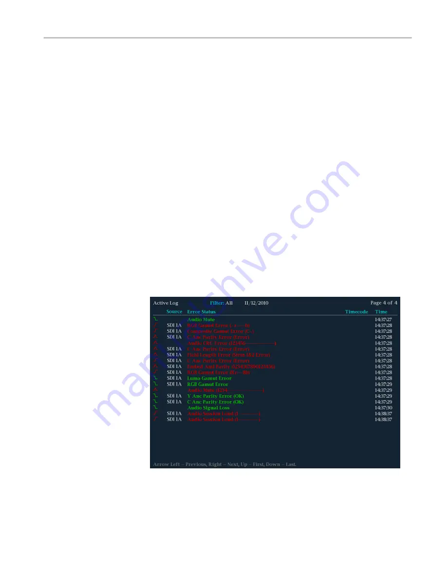
Error Log display

The Error Log display shows a log of the error events that have been detected
since the instrument was turned on or since the log was last reset. You can view
all of the errors or just the errors for the selected input and save the log to a USB
memory device. 

Figure 41: Error Log display


Display modes

WFM2300 and WFM2200A Waveform Monitors User Manual 

123

Summary of Contents for WFM2200A

Page 1: ...WFM2300 and WFM2200A Multiformat Multistandard Portable Waveform Monitors User Manual P077086502 077 0865 02 ...

Page 2: ......

Page 3: ...WFM2300 and WFM2200A Multiformat Multistandard Portable Waveform Monitors User Manual www tektronix com 077 0865 02 This document supports software version 2 11 X and above ...

Page 4: ...d and pending Information in this publication supersedes that in all previously published material Specifications and price change privileges reserved TEKTRONIX and TEK are registered trademarks of Tektronix Inc Contacting Tektronix Tektronix Inc 14150 SW Karl Braun Drive P O Box 500 Beaverton OR 97077 USA For product information sales service and technical support In North America call 1 800 833 ...

Page 5: ...s taxes and any other charges for products returned to any other locations This warranty shall not apply to any defect failure or damage caused by improper use or improper or inadequate maintenance and care Tektronix shall not be obligated to furnish service under this warranty a to repair damage resulting from attempts by personnel other than Tektronix representatives to install repair or service...

Page 6: ......

Page 7: ...r requirements 7 Connect power 8 Power on and power off procedures 12 Tripod installation 15 SFP module installation 15 Video system installation 17 To test cable margins WFM2300 only 19 To measure A V delay or propagation time Option AVDP only 20 Configure the network interface 20 Configure the IP address 20 Enable the Web remote interface 22 Configure and enable SNMP control 22 Incoming inspecti...

Page 8: ...ls 41 Multi In signals 41 ASI transport streams WFM2300 Option ASI only 41 External reference signals 41 Dual link signals 42 Connectors 43 Connector configuration 43 Signal outputs 44 SDI video output 44 AES audio output 45 A V delay or propagation time signal output Option AVDP only 46 SFP module receiver transceiver Option SFP only 46 Display modes ANC Data display Option DATA only 48 To access...

Page 9: ...lume 64 Audio Generator Status display 65 To access the Audio Generator Status display 65 Elements of the Audio Generator Status display 65 Generator pop up menu Audio Generator Status display 67 CONFIG menu 70 Dolby E metadata configuration Option DBE only 70 Dolby E generated formats Option DBE only 71 Dolby E loudness measurements 76 AV Delay Measurement display Option AVDP only 78 To access th...

Page 10: ... display 92 To access the External Reference Waveform display 92 Elements of the External Reference Waveform display 92 Waveform pop up menu External Reference Waveform display 93 CONFIG menu 93 To position the External Reference Waveform trace 93 Eye display WFM2300 only 94 Elements of the Eye display 95 Eye display pop up menu 95 Usage notes 96 Jitter display WFM2300 only 96 Elements of the Jitt...

Page 11: ...12 Audio Session display 115 Auxiliary Data Status display 118 Dolby Audio Status display 121 Error Log display 123 SFP Module Status display Option SFP or Option SFP HDMI 126 SDI Status display WFM2300 only 128 Video Session display 131 Timing Measure display 136 To access the Timing Measure display 136 Elements of the Timing Measure display 136 Measure pop up menu Timing Measure display 137 Timi...

Page 12: ...sors Waveform display only 156 Cursor types 156 To display and adjust the cursors 156 Display capture freeze 158 Remote screen capture 158 Line Select 159 Audio volume and source adjustment 160 To adjust the audio volume 160 To select the audio source 161 Presets 161 Preset groups 161 To save presets 162 To rename groups or presets 162 To recall presets 163 To export presets to a USB device 163 To...

Page 13: ...eye measurements 190 Eye measurement set up 191 To make manual eye measurements 191 To manually measure aberrations 192 To manually measure rise time using variable gain 193 To make automatic eye measurements 194 To make jitter measurements 194 To manually measure jitter 196 Taking cable loss measurements 197 Checking chroma luma delay Check chroma luma delay using the Lightning display 199 Checki...

Page 14: ...ed 16 channel audio 225 To configure audio inputs for embedded 16 channel audio 225 To set the audio input for embedded 16 channel audio 225 To quickly select channels 1 8 or 9 16 of the embedded audio 226 To check surround sound 227 Elements of the surround sound display 228 Usage notes 229 Closed captioning CC teletext AFD and safe area compliance Monitoring CC and teletext 231 To configure CC a...

Page 15: ... command conflicts 240 Application examples Timing a Studio Using the traditional method 241 Timing a Studio Using the timing display method 242 To use the timing display to time a signal to a reference 243 Timing a Studio Timing multiple inputs to a router 244 To time the inputs to a router 244 Usage notes 245 Troubleshooting cable problems 246 Table of Contents WFM2300 and WFM2200A Waveform Moni...

Page 16: ...Table of Contents x WFM2300 and WFM2200A Waveform Monitors User Manual ...

Page 17: ... operation of the product it is essential that you follow generally accepted safety procedures in addition to the safety precautions specified in this manual The product is designed to be used by trained personnel only Only qualified personnel who are aware of the hazards involved should remove the cover for repair maintenance or adjustment Before use always check the product with a known source t...

Page 18: ...learly mark the product to prevent its further operation Examine the exterior of the product before you use it Look for cracks or missing pieces Use only specified replacement parts Replace batteries properly Replace batteries only with the specified type and rating Recharge batteries properly Recharge batteries for the recommended charge cycle only Do not operate in wet damp conditions Be aware t...

Page 19: ...f the product power and disconnect the power cord from the mains power before removing any covers or panels or opening the case for servicing Use care when servicing with power on Dangerous voltages or currents may exist in this product Disconnect power remove battery if applicable and disconnect test leads before removing protective panels soldering or replacing components Terms in the manual The...

Page 20: ...s a hazard to property including the product Symbols on the product When this symbol is marked on the product be sure to consult the manual to find out the nature of the potential hazards and any actions which have to be taken to avoid them This symbol may also be used to refer the user to ratings in the manual The following symbols may appear on the product Important safety information xiv WFM230...

Page 21: ...Tektronix part number Installation and safety Installation and Safety Instructions Provides installation safety general specifications and compliance information This is a printed manual and is also available on the Web at www tektronix com downloads 071 3205 XX Instrument operation User Manual this manual Provides in depth descriptions of instrument operation Available on the Web at www tektronix...

Page 22: ...recycling information for the Lithium Ion battery pack This is a printed manual and is also available on the Web at www tektronix com downloads 075 1041 XX Information about the WFM200BC battery charger WFM200BC External Battery Charger Instructions Provides safety and operating information for the optional external battery charger This is a printed manual and is also available on the Web at www t...

Page 23: ...ions with a large 6 5 inch high brightness low power consumption LED backlit display and weighing in at less than 4 4 lbs 2 kg These instruments provide an array of basic monitoring tools for video SD HD Dual Link and optional 3G and audio Embedded and AES signals You can configure the instrument for a full screen or quad tile display which allows you to see all of the necessary signal information...

Page 24: ...e Moving Picture function on the output signal Option DBE supports Dolby E test stream generation for embedded and AES outputs which provides easy access to Dolby E audio reference and test signals within modern broadcast facilities These signals include test tones at different levels 18 dB 20 dB and Multi tone with frame rates compatible with the respective video signals Waveform display Traditio...

Page 25: ... propagation time measurement that measures the time between video signals leaving and returning to the instrument This measurement allows the facility engineer to align the timing of the multiple incoming videos check the delay of a CODEC system and or a video signal path including the satellite feed MPEG2 transport stream monitoring WFM2300 Option ASI only Support for monitoring an ASI MPEG2 tra...

Page 26: ...ing measurement and Dolby E test signals user configurable parameters include Tone 18 dB 20 dB and Multitone Configuration 8x1 mono 4x2 stereo surround 5 1 5 1 2 and 7 1 Metadata and Dolby E audio frame start location LOUD Add Audio Loudness monitoring capabilities including Loudness Meter SFP Add Optical input output SDI module support includes one SFP module an SFP module is available for additi...

Page 27: ... the following power cord options Power cords for use in North America are UL listed and CSA certified Cords for use in areas other than North America are approved by at least one authority acceptable in the country to which the product is shipped Table 5 Power cord options Option Description A0 North America power A1 Universal EUR power A2 United Kingdom power A3 Australia power A5 Switzerland po...

Page 28: ...ailable if the instrument is within product warranty It is not available once instrument exits warranty period Installation Your handheld instrument is shipped in a fully enclosed metal chassis with a protective rubber boot A flange with a threaded hole is provided on the bottom panel for use with a tripod mount If you need to install your instrument in a custom application such as a console be su...

Page 29: ... Hz the operating voltage range must be from 100 to 240 VAC continuous The typical power draw is 27 W However if you are operating the instrument and charging a battery at the same time the typical power doubles to 54 W WARNING To reduce risk of fire and shock make sure the mains supply voltage fluctuations do not exceed 10 of the operating voltage range Systems with both current carrying conducto...

Page 30: ...properly operate and maintain the battery pack CAUTION To avoid damage to the battery pack use only the waveform monitor or the optional WFM200BC battery charger to charge the battery pack Do not connect any other voltage source to the battery pack To avoid overheating of the battery pack during charging do not exceed the allowable ambient temperature of 0 to 40 C The battery pack will stop chargi...

Page 31: ...trument top panel as shown below NOTE If a battery pack is installed in the instrument it will automatically charge whenever the supplied AC adapter is connected whether the instrument is On Off or in Standby mode Getting started WFM2300 and WFM2200A Waveform Monitors User Manual 9 ...

Page 32: ...replaced while the instrument is turned on and operating with the AC adapter See the WFM200BA Rechargeable Battery Pack Instructions for more information about the battery pack 1 On the rear panel of the instrument remove the cover for the battery compartment a Use your fingers or a coin to turn the battery cover screw counterclockwise until the cover is loose b Lift away the battery cover 2 Inser...

Page 33: ...ry pack tab as shown below 4 Replace the battery compartment cover a Insert the three tabs on the battery cover into the chassis slots as shown below Getting started WFM2300 and WFM2200A Waveform Monitors User Manual 11 ...

Page 34: ... to the instrument AC adapter Connect the AC adapter to the power connector on the instrument See Power cord installation on page 9 Battery pack Install the WFM200BA battery pack See Battery pack installation on page 10 2 Press the Power button on the instrument front panel to turn the instrument on 3 If you are powering the instrument using only the battery pack check the power level before opera...

Page 35: ...t 5 seconds for the instrument to automatically power off Standby Use the arrow buttons to select Standby to put the instrument in Standby mode In Standby mode the instrument consumes less power than when it is turned on and also takes less time to turn back on than when the instrument is turned completely off Cancel Use the arrow buttons to select Cancel if you want to cancel the power off operat...

Page 36: ...minated on the top panel of the instrument next to the power connector and beneath the battery icon The charge level meter is shown on the bottom right of the status bar The following table shows examples of the meter icons Table 7 Battery charge level meter icons Item Description Battery fully charged AC adapter plugged in Battery partially charged AC adapter plugged in and charging Battery level...

Page 37: ... tripod as shown below SFP module installation There are two SFP modules available With Option SFP you receive an SFP module for monitoring or outputting optical SDI signals With Option SFP HDMI you receive an SFP module for monitoring HDMI signals Getting started WFM2300 and WFM2200A Waveform Monitors User Manual 15 ...

Page 38: ...anel of the waveform monitor as shown below optical SFP module shown The module will latch into place when fully inserted SFP module removal To remove the SFP module lift up on the latch and then pull the module out of the SFP connector as shown below optical SFP module shown Getting started 16 WFM2300 and WFM2200A Waveform Monitors User Manual ...

Page 39: ...ation of the optional SFP input is determined by the installed module No termination occurs for optical inputs Compatibility of BNC center pins Most BNC connectors for video equipment whether 50 Ω or 75 Ω use a 50 Ω standard center pin Some laboratory 75 Ω BNC connectors use a smaller diameter center pin The BNC connectors on the instrument are designed to work with the 50 Ω standard large diamete...

Page 40: ...ument To genlock the SDI output test signal to the external reference signal To genlock the SDI output test signal to the external reference signal use the CONFIG Video Gen Outputs Test Signal Genlock menu to enable the genlock function and to configure the genlock vertical and horizontal timing offsets The Generator Status display and the Status Bar indicate the status of the genlock function Get...

Page 41: ...a cable from the other connector of the STRESS LOOP to the SDI A input as shown below Stress loop connections for a generated signal To test the cable margins for a generated signal route the SDI OUT signal to one of the STRESS LOOP connectors Route a cable from the other connector of the STRESS LOOP to your video system as shown below Getting started WFM2300 and WFM2200A Waveform Monitors User Ma...

Page 42: ...wing Accessing the remote interface of the instrument Remotely controlling the instrument using SNMP commands Upgrading the instrument software Configure the IP address Perform the following steps to configure the IP address of the instrument 1 Make one of the following Ethernet connections If you have a local Ethernet network connect the instrument and computer to the network If you do not have a...

Page 43: ... If you connected the instrument to your local network select either Manual or DHCP as directed by your LAN administrator If you connected the instrument directly to your computer select Manual d If you set the IP configuration mode to Manual perform one of the following tasks If you connected the instrument to your local Ethernet network enter the IP address subnet mask and gateway address as dir...

Page 44: ...o Web Password and press the right arrow key to change the menu focus to the submenu This opens the Web Password display b Use the left right arrow keys to move the highlight to the desired box in the password Use the up down arrow keys or the knob to change the text in each box as required c To accept clear or cancel your changes move the highlight to the respective selection box and press the SE...

Page 45: ... the left and right arrow keys to move the highlight to each box in the string For each box in the string use the up and down arrow keys to change the entry as required for your installation c To accept clear or cancel the changes select the appropriate selection box and press the SEL button 4 Set the SNMP trap addresses as follows You can configure up to four IP addresses to which SNMP traps are ...

Page 46: ...n diagnostic page should appear on the screen 4 Verify that all self tests pass Any failures are shown in red NOTE Although the results of the power on diagnostics are erased from the screen during the power on process you can view the results by selecting or by viewing them on the instrument Web page 5 After the diagnostics are finished the instrument state is restored When the progress indicator...

Page 47: ...At low temperatures the fans will turn slowly and be very quiet Storing or shipping the instrument CAUTION To prevent damage to the Li Ion battery pack and the instrument observe the following precautions when storing or shipping the instrument Do not store the battery pack in the instrument when the instrument is not in use Remove the battery pack before shipping the instrument To repackage the L...

Page 48: ...packaging If you cannot use the original packaging materials to package the instrument follow these directions a Obtain a carton of corrugated cardboard having inside dimensions six or more inches greater than the dimensions of the instrument Use a shipping carton that has a test strength of at least 250 pounds 113 5 kg b Surround the module with a protective anti static bag c Pack dunnage or uret...

Page 49: ...ing the waveform display mode from RGB to YPbPr To display a pop up menu press and hold the desired button for about two seconds Instrument wide settings The parameters in the Configuration menu are instrument wide settings The configuration menu controls settings that are changed only occasionally such as changing waveform color or setting the network address Scope of controls Some controls are g...

Page 50: ...ess the Preset menu See Presets on page 161 Measurement buttons WFM VECTOR PICT AUDIO GAMUT STATUS MEAS GEN PHY Press these buttons to select one of the instrument displays See To select a display on page 32 Scaling buttons SWEEP MAG GAIN VAR Press these buttons to select how the signal trace is displayed See Gain sweep and magnification on page 153 LINE Press this button to enable or disable the ...

Page 51: ...ton to access menu selections to adjust various display levels to enable the Infinite Persistence mode and to save a copy of the instrument display to a device connected to the USB port Press the MAIN button to access menu selections to select the tile display mode to check the USB port status and to configure the function of the Display Select button selecting a display or turning the Thumbnail v...

Page 52: ...arameter is controlled by the knob POS Press the POS position button and then use the General knob to position traces on the Waveform Vector Lightning and Bowtie displays Use the up down arrow buttons for finer adjustments and use the left right arrow buttons to switch between horizontal and vertical adjustments VOL Press the VOL volume button and then use the General knob and the up down arrow bu...

Page 53: ...help To navigate online help 1 Press the HELP button to open online help 2 Press the right arrow key to navigate to the one of the three panes Help Contents Help Index or the right side pane that contains the topic content related to the front panel button you press while help is activated or the links in the help files and menus you use 3 Use the General knob or the up down arrow keys to highligh...

Page 54: ...FM2300 only Status Error Log Alarm Status Video Session Audio Session Dolby Status Audio Control AES Channel Status Auxiliary Data Status SDI Status SDI ASI Status WFM2300 only SFP Status Audio Phase Surround Picture Picture frame on off and various closed caption and safe area graticules Generator Generator Status Diagnostics Monitor Phy WFM2300 only Eye Jitter To select a display Push a front pa...

Page 55: ...utton for three seconds To hide a pop up menu press the specified button again Pop up menus appear in the active tile and in general control only settings specific that tile A pop up menu will not appear if it is not appropriate for the current instrument setting To set display parameters Use the pop up menus to set up the measurements that you display 1 Select a tile by pressing the Display Selec...

Page 56: ... the Waveform Vector or Gamut displays The Waveform Vector or Gamut display must be in full screen mode to activate the thumbnail view Button configuration Perform the following steps to configure the function of the DISPLAY SELECT button 1 Press the MAIN button to display the Main menu 2 Navigate to Display Select 3 Press the right arrow key to select Thumb or Tile Sel 4 Press the MAIN button to ...

Page 57: ...lated tile numbers In full screen mode press the DISPLAY SELECT button to change the display to the next tile In full screen mode the same four displays are available as in 4 tile mode Press and hold the DISPLAY SELECT button to toggle between 4 tile and full screen mode The selected active tile in 4 tile mode is the tile expanded to full screen mode NOTE You can also use the Main menu to toggle b...

Page 58: ...Figure 4 Changing from 4 tile to full screen view Getting acquainted with your instrument 36 WFM2300 and WFM2200A Waveform Monitors User Manual ...

Page 59: ...re display in any tile press the DISPLAY SELECT button to toggle the thumbnail view of the picture display on and off The button stays illuminated when the thumbnail view is turned on In 4 tile mode the placement of the thumbnail view is determined automatically However the placement is usually in the highest numbered tile containing a trace display and then on status displays The following figure...

Page 60: ... When the reference source is set to internal Internal is always displayed When the reference source is set to external the text indicates the reference format such as NTSC or whether the reference is missing or unlocked Genlock status Icon indicating the status of the reference signal used for the genlock output of the SDI test signal The color of the icon indicates the status Blue indicates that...

Page 61: ...me A readout showing the name assigned to the instrument in the CONFIG Network Settings menu Audio status or ASI status An up to 32 character string indicating the selected audio input AES A or the embedded audio channel status when embedded audio is the selected input In the latter case each character shows the status of a specific channel for not present and P for present For ASI transport strea...

Page 62: ...t from the remote interface Alarms Disabled This text appears in the Status Bar when Alarms are disabled from the Configuration menu Freeze Active Appears when the tiles are frozen or captured Battery Low This icon appears only when the instrument is using a battery pack as the power source This icon appears when the battery has less than 10 minutes of operating power remaining The icon turns from...

Page 63: ...ansport streams WFM2300 Option ASI only Connect an ASI transport stream to the SDI A or MULTI IN connectors on the top of the instrument See also Video system installation on page 17 Use the CONFIG menu to set the parameters for monitoring the transport stream such as alarms monitored External reference signals The reference input is internally terminated in 75 Ω Reference signals can be analog vi...

Page 64: ...er display The instrument will automatically detect properly formatted dual link signals which contain a SMPTE352 VPID in both links as required by SMPTE 372 In this case set the format structure and transport settings in the CONFIG SDI Input submenu to Auto to enable automatic detection of dual link signals If the SMPTE352 VPID is missing the instrument may be forced into dual link input mode by ...

Page 65: ...elected input A or B is illuminated When Option 3G is installed and you are monitoring a 2xHD 3 Gb s SDI signal as defined by SMPTE 425 you can press and hold the associated input button to open a pop up menu where you can select which stream in the signal to monitor Possible menu options include the following SDI Input 1A or Multi In 1B SFP Input 2A or SFP Input 2B Displays the 2 HD streams of a ...

Page 66: ...he metadata CONFIG Audio Inputs Outputs select the embedded audio signal channel format and mapping and set the volume for the instrument speakers and headphone output Signal outputs SDI video output This instrument can generate SD SDI and HD SDI signals using the SDI OUT connector With Option 3G installed it can also generate a 3 Gb s SDI test signal The following signals can be generated in Leve...

Page 67: ...G menu to set the vertical and horizontal timing offsets used by the genlock function The genlock status icon in the Status Bar indicates the genlock status See Status bar icons on page 40 AES audio output This instrument can generate the following AES audio signals Test signal AES test tones with user configurable frequency amplitude and bitdepth AES out loopthrough output of the signal on the MU...

Page 68: ... how you should configure the SFP The instrument will store the configuration for each SFP module installed by the module s vendor name and part number so that when you reinstall a recognized module the related configuration will be automatically applied You can configure the module from the CONFIG Input Mode SFP Module Config menu When installing a module for the first time select from the follow...

Page 69: ... on page 94 Jitter display WFM2300 only on page 96 Lightning display on page 98 LTC Waveform display on page 101 Picture display on page 103 Split Diamond display on page 106 Status displays AES Channel Status display on page 109 Alarm Status display on page 110 ARIB Status displays on page 112 Audio Control Packet display on page 112 Audio Session display on page 115 Auxiliary Data Status display...

Page 70: ...ntinually monitors the signal and tells you when changes in the presence of data occur When Watch List mode is activated the instrument displays the presence and status of ANC data types you have selected in the Watch List This allows you to focus on the ANC data types that are important to you To access the ANC Data display 1 Press and hold the MEAS button to open the Measure pop up menu 2 Use th...

Page 71: ...l value with parity bits added is displayed in parentheses mutually exclusive with DBN field DBN Data Block Number of the acquired packet values range from 0 to 0xFF the actual value with parity bits added is displayed in parenthesis mutually exclusive with SDID field DC Data Count word of the acquired packet the number of User Data words is displayed in decimal the actual value with parity bits a...

Page 72: ...t Disp WFM2300 Option ASI only For MPEG2 transport stream inputs displays the MPEG TS PID tree with each stream element having an LED icon to indicate the status of the element See ASI PID List display WFM2300 Option ASI only on page 54 All sessions reset Select this option and press the SEL button to globally reset all of the displayed ANC Data display sessions The session time is set to zero and...

Page 73: ...s and hold the MEAS button and select Display Type and then ANC Data Display from the pop up menu You can now view the data types you checked in the Watch List Arrowhead display The Arrowhead display is a Tektronix proprietary display that shows gamut violations of the SDI input if translated into the Composite domain NTSC and PAL For more information about using the gamut checking displays See Di...

Page 74: ...ates the threshold settings using blue dashed lines Luma minimum Shows the currently specified minimum luma threshold Luma Min setting in the CONFIG Gamut Thresholds menu Luma maximum Shows the currently specified maximum luma threshold Luma Max setting in the CONFIG Gamut Thresholds menu Y Area and Y C Area Shows the specified percentage of the total image pixels that can be outside the current l...

Page 75: ... 106 CONFIG menu Use the CONFIG menu to set the following Arrowhead display parameters Use the menu selections under Gamut Thresholds to set the minimum and maximum gamut limits for composite signals derived from the SDI signal set the minimum and maximum luma levels specify the percentage of the total image pixels that can be outside the current gamut or luma limits and not generate error reports...

Page 76: ...gnal Sync byte errors and continuity counter errors are logged in the error report to help users investigate intermittent issues The instrument also performs Eye pattern measurement on the ASI stream to ensure signal quality in the physical layer To access the ASI PID List display 1 Press and hold the MEAS button to open the Measure pop up menu 2 Use the arrow keys to select Display Type ASI PID L...

Page 77: ...f the TSDT TableID Shows the table_id value of the TSDT Program Association Table PAT One or more transport packets with a PID value and table_id value of 0x00 For the PAT icon the following text is displayed PID Shows the PID value of the PAT Table Shows the table_id value of the PAT Stream Shows the transport_stream_id value of the PAT Programs Shows the number of programs contained in the trans...

Page 78: ...the data stream Type Shows the type of the data stream Digital Storage Media Command and Control DSM CC One or more transport packets with a PID value specified by the elementary_PID in the PMT and a stream_type value of 0x08 For the DSM CC icon the following text is displayed PID Shows the PID value of the data DSM CC Type Shows the type of the DSM CC GHOST One or more transport packets with a PI...

Page 79: ...HEG 0x28 to 0x7F Reserved 0x8 Annex A DSM CC 0x80 DigiCipher 2 0x9 ITU T Rec H 222 1 0x81 Dolby AC 3 Audio 0xA DSM_CC MPE 0x82 User Private 0xB DSM_CC U N Messages 0x83 SCTE Isochronous Data 0xC DSM_CC Descriptors 0x84 to 0x86 User Private 0xD DSM_CC Sections 0x87 Dolby E AC 3 Audio 0xE MPEG 2 Auxiliary 0x88 SMPTE MS VC 1 Video 0xF Advanced Audio Codec AAC 0x89 to 0x8F User Private 0x10 MPEG 4 Vid...

Page 80: ...a video signal See ANC Data display Option DATA only on page 48 AV Delay Option AVDP only Displays results of the AV Delay and Propagation Time measurements See AV Delay Measurement display Option AVDP only on page 78 ASI PID List Disp WFM2300 Option ASI only For MPEG2 transport stream inputs displays the MPEG TS PID tree with each stream element having an LED icon to indicate the status of the el...

Page 81: ... the channel levels in a surround sound listening environment 3 Press the AUDIO button to close the pop up menu Elements of the Audio display Figure 13 Audio display Surround mode Level meters Shows the audio levels See To check audio level on page 222 The response of the level meters is determined by the ballistics setting in the CONFIG Digital Audio Displays menu Phase or Surround Display Select...

Page 82: ...cale dBFS for digital inputs and dB relative to 0 775 Volts dBu for analog inputs The 0 dB mark is digital Full scale for digital inputs and 0 dBu for analog inputs You may also set the 0 dB mark to either the Peak Program level or the Test level Above bar warning messages This instrument displays warning messages above the level meter bars The warning messages that can appear above the bars as fo...

Page 83: ... ignored and the audio sample as treated as normal audio When the Ignore Validity Bit setting is set to Off then the Validity bit value is used to mute the audio when the bit value is high NO AUDIO Indicates that an AES or embedded input has the Non audio bit set NOT PRESENT Indicates that an audio channel is not present in the current audio input DOLBY D Indicates an AES or embedded input is DOLB...

Page 84: ...r the Embedded A Embedded B or Embedded Dual Link selections Emb 16 Ch Sets the audio source to be from the embedded audio on the currently selected video input This mode displays level meters for all 16 channels in the embedded audio but does not display the correlation meters nor the Phase or Surround Sound auxiliary displays NOTE When the audio input source is set to Emb 16 Ch Emb 1 8 or Emb 9 ...

Page 85: ...and R axes in the vertical and horizontal positions respectively Dominance indicator When Surround Display is selected as the auxiliary display use this menu selection to turn the dominance indicator on and off When on it indicates the location of the dominant sound in the surround sound image using a cross hairs pointer Phase Headphone pair Select which audio pairs are mapped to the headphone jac...

Page 86: ...settings Use the menu selections under Alarms Audio Content and Alarms AES Embedded to enable various audio alarms To adjust audio volume You can use any of the following methods to adjust the volume of the audio played out on the instrument speakers or the headphone jack WARNING To prevent the risk of hearing damage always turn down the audio volume before connecting headphones to the instrument ...

Page 87: ... Generator Status display 1 Press and hold the GEN button to open the Generator pop up menu 2 Use the arrow keys to select Display Type Audio Generator 3 Press the GEN button to close the pop up menu Elements of the Audio Generator Status display Figure 14 Audio Generator Status display Display modes WFM2300 and WFM2200A Waveform Monitors User Manual 65 ...

Page 88: ...eo input Tone Frequency Shows the test tone audio frequencies for channel 1 and channel 2 when the AES Output setting is Test Tone Tone Amplitude Shows the test tone audio amplitudes for channel 1 and channel 2 when the AES Output setting is Test Tone Tone Bitdepth Shows the test tone audio bitdepth 20 bit or 24 bit when the AES Output setting is Test Tone NOTE The above tone frequency amplitude a...

Page 89: ...ix Pref Shows the Dolby E metadata downmix preferred setting DE LtRt CMix Lev Shows the Dolby E metadata LtRt center mix level setting DE LtRt SMix Lev Shows the Dolby E metadata LtRt surround mix level setting DE LoRo CMix Lev Shows the Dolby E metadata LoRo center mix level setting DE LoRo SMix Lev Shows the Dolby E metadata LoRo surround mix level setting Generator pop up menu Audio Generator S...

Page 90: ...ls both the number of programs in the stream as well as how the eight audio channels are allocated to the programs You can select from 5 1 2 20b 5 1 20b 5 1 16b 7 1 20b 4x2 20b and 8x1 20b DE Audio Level When Option DBE is installed sets the level of the Dolby E signal to 18 dBFS 20 dBFS or Multi Tone DE Start Position When Option DBE is installed sets the starting position of the Dolby E signal t...

Page 91: ... Standard Music Light Speech or Disable Cen Mix Lev Sets the center downmix level of the Dolby E signal This parameter indicates what level shift should be applied to the center channel before adding it to the left and right channels when downmixing to a stereo output This parameter is used when extended BSI parameters are not active You can select 3 0 dB 4 5 dB or 6 0 dB Surr Mix Lev Sets the sur...

Page 92: ... pop up menu are duplicated in the CONFIG Video Gen Outputs and the CONFIG Audio Gen Outputs menus Changes made in the Generator Status pop up menu immediately appear in the CONFIG Outputs and the CONFIG Audio Gen Outputs menu selections Dolby E metadata configuration Option DBE only NOTE Use caution when changing the Dolby E metadata values Changing the metadata does not change the encoded audio ...

Page 93: ...rogram 1 C Program 1 R Program 1 Ls Program 1 Rs Program 1 LFE Program 1 Lt Program 1 Rt 20 dBSF 20 dBFS 2 398 kHz 20 dBFS 2 398 kHz 20 dBFS 2 398 kHz 20 dBFS 2 398 kHz 20 dBFS 2 398 kHz 20 dBFS 240 Hz 20 dBFS 2 398 kHz 20 dBFS 2 398 kHz 18 dBSF 18 dBFS 2 398 kHz 18 dBFS 2 398 kHz 18 dBFS 2 398 kHz 18 dBFS 2 398 kHz 18 dBFS 2 398 kHz 18 dBFS 240 Hz 18 dBFS 2 398 kHz 18 dBFS 2 398 kHz Multitone 18 ...

Page 94: ... Program 1 Lt Program 1 Rt 20 dBSF 20 dBFS 2 400 kHz 20 dBFS 2 400 kHz 20 dBFS 2 400 kHz 20 dBFS 240 Hz 20 dBFS 2 400 kHz 20 dBFS 2 400 kHz 20 dBFS 2 400 kHz 20 dBFS 2 400 kHz 18 dBSF 18 dBFS 2 400 kHz 18 dBFS 2 400 kHz 18 dBFS 2 400 kHz 18 dBFS 240 Hz 18 dBFS 2 400 kHz 18 dBFS 2 400 kHz 18 dBFS 2 400 kHz 18 dBFS 2 400 kHz Multitone 18 dBFS 240 Hz 20 dBFS 360 Hz 22 dBFS 480 Hz 24 dBFS 600 Hz 26 dB...

Page 95: ...gram 1 LFE Program 1 Lt Program 1 Rt 20 dBSF 20 dBFS 1 0 kHz 20 dBFS 1 0 kHz 20 dBFS 1 0 kHz 20 dBFS 1 0 kHz 20 dBFS 1 0 kHz 20 dBFS 240 Hz 20 dBFS 1 0 kHz 20 dBFS 1 0 kHz 18 dBSF 18 dBFS 1 0 kHz 18 dBFS 1 0 kHz 18 dBFS 1 0 kHz 18 dBFS 1 0 kHz 18 dBFS 1 0 kHz 18 dBFS 240 Hz 18 dBFS 1 0 kHz 18 dBFS 1 0 kHz Multitone 18 dBFS 250 Hz 20 dBFS 350 Hz 22 dBFS 475 Hz 24 dBFS 600 Hz 26 dBFS 1200 Hz 28 dBFS...

Page 96: ...ram 1 Lt Program 1 Rt 20 dBSF 20 dBFS 2 997 kHz 20 dBFS 2 997 kHz 20 dBFS 2 997 kHz 20 dBFS 2 997 kHz 20 dBFS 2 997 kHz 20 dBFS 240 Hz 20 dBFS 2 997 kHz 20 dBFS 2 997 kHz 18 dBSF 18 dBFS 2 997 kHz 18 dBFS 2 997 kHz 18 dBFS 2 997 kHz 18 dBFS 2 997 kHz 18 dBFS 2 997 kHz 18 dBFS 240 Hz 18 dBFS 2 997 kHz 18 dBFS 2 997 kHz Multitone 18 dBFS 239 8 Hz 20 dBFS 359 7 Hz 22 dBFS 479 5 Hz 24 dBFS 599 4 Hz 26...

Page 97: ...gram 1 LFE Program 1 Lt Program 1 Rt 20 dBSF 20 dBFS 3 0 kHz 20 dBFS 3 0 kHz 20 dBFS 3 0 kHz 20 dBFS 3 0 kHz 20 dBFS 3 0 kHz 20 dBFS 240 Hz 20 dBFS 3 0 kHz 20 dBFS 3 0 kHz 18 dBSF 18 dBFS 3 0 kHz 18 dBFS 3 0 kHz 18 dBFS 3 0 kHz 18 dBFS 3 0 kHz 18 dBFS 3 0 kHz 18 dBFS 240 Hz 18 dBFS 3 0 kHz 18 dBFS 3 0 kHz Multitone 18 dBFS 240 Hz 20 dBFS 360 Hz 22 dBFS 480 Hz 24 dBFS 600 Hz 26 dBFS 1200 Hz 28 dBFS...

Page 98: ...s values use the PRESET menu to create a preset with the specific values you want Table 14 Dolby E loudness measurements 23 98 and 24 Hz frame rates Dolby E program Dolby E level Loudness measurement values LKFS Program 1 Program 2 Program 3 Program 4 Program 5 Program 6 Program 7 Program 8 8x1 20 dBSF 20 2 20 2 20 2 20 2 20 2 20 2 20 2 20 2 18 dBSF 18 2 18 2 18 2 18 2 18 2 18 2 18 2 18 2 Multiton...

Page 99: ...0 0 18 dBSF 18 0 18 0 18 0 18 0 Multitone 20 1 23 6 27 0 28 5 Table 16 Dolby E loudness measurements 29 97 and 30 Hz frame rates Dolby E program Dolby E level Loudness measurement values LKFS Program 1 Program 2 Program 3 Program 4 Program 5 Program 6 Program 7 Program 8 8x1 20 dBSF 19 9 19 9 19 9 19 9 19 9 19 9 19 9 19 9 18 dBSF 17 9 17 9 17 9 17 9 17 9 17 9 17 9 17 9 Multitone 22 5 23 9 25 7 27 ...

Page 100: ... measurement allows facility engineers to align the timing of the multiple incoming videos check the delay of a CODEC system and or a video signal path including the satellite feed In Propagation mode the video and audio on the SDI OUT signal are continuously cycled between being on for 0 5 seconds then set to black and muted for 9 5 seconds NOTE The amount of time that the AV Delay or Propagation...

Page 101: ... manual offset value Adjusted AV Delay Shows the adjusted timing difference Propagation Time Shows the propagation time measurement Measure pop up menu AV Delay display Press and hold the MEAS button to open the Measure pop up menu The pop up menu enables you to configure the display type and configure display parameters for the different display types The following menu selections are available D...

Page 102: ... element See ASI PID List display WFM2300 Option ASI only on page 54 AV Delay Enable Enables or disables the delay measurement However if the AV Timing Mode is set to AV Delay or Propagation the instrument will still be outputting the measurement signal on the SDI OUT connector Clear Offset Clears the saved offset from the AV Delay measurement Save Offset When making AV Delay measurements only sav...

Page 103: ... null A relative amplitude error will decrease the depth of the null An incomplete null combined with an offset from center indicates both amplitude and timing problems between the channels being compared To access the Bowtie display 1 Press and hold the MEAS button to open the Measure pop up menu 2 Use the arrow keys to select Display Type Bowtie 3 Press the MEAS button to close the pop up menu E...

Page 104: ...TA only Displays the content of all digital signal formats structures and transports SD HD 3G dual link 4 2 2 4 4 4 and others except for composite signals See Datalist display Option DATA only on page 83 Bowtie Displays the interchannel timing between Y Pb and Y Pr ANC Data Option DATA only Displays all of the ANC data in a video signal See ANC Data display Option DATA only on page 48 AV Delay Op...

Page 105: ...al knob or use the up down arrow keys to adjust the position of the waveform 4 Press the POS button to turn off the position adjustment mode Datalist display Option DATA only The Datalist display allows you to see SD HD or 3G Option 3G only data without any interpolation The Datalist tool examines the contents of all digital formats structures and transports SD HD dual link 3 Gb s 4 2 2 4 4 4 and ...

Page 106: ...tton to switch between Line Select and Word Select Samp Shows the sample number Y0 Cb Cr Y1 These labels change based on the signal but they show the line number for each component Datalist color coding Different fields of the data stream are shown in different colors Green Active video data Blue Data in horizontal or vertical blanking intervals White EAV and SAV packets other reserved values such...

Page 107: ...Delay Measurement display Option AVDP only on page 78 ASI PID List Disp WFM2300 Option ASI only For MPEG2 transport stream inputs displays the MPEG TS PID tree with each stream element having an LED icon to indicate the status of the element See ASI PID List display WFM2300 Option ASI only on page 54 Trace type Select from the following trace types Video is the default setting Video This mode show...

Page 108: ...that will highlight data as errors Diagnostics Monitor display The Diagnostics Monitor display shows the status of various instrument diagnostics Use the up and down arrow keys to navigate through the different pages of the display To access the Diagnostics Monitor display 1 Press and hold the GEN button to open the Generator pop up menu 2 Use the arrow keys to select Display Type Diag Monitor 3 P...

Page 109: ...Figure 19 Diagnostics Monitor display page 2 Figure 20 Diagnostics Monitor display page 3 Display modes WFM2300 and WFM2200A Waveform Monitors User Manual 87 ...

Page 110: ...or display Elements on page 1 The following instrument diagnostic information appears on page 1 of the display See Diagnostics Monitor display on page 86 Fan Speed rpm Shows the current speed of both internal fans and the high and low speed measurements for each fan since the instrument was turned on Temperatures Shows the last low high and average temperatures for various internal components Elem...

Page 111: ...eing generated by the instrument See Video Generator Status display on page 144 Audio Generator Status Displays the status of audio signals being generated by the instrument See Audio Generator Status display on page 65 Diagnostics Monitor Displays the status of various instrument diagnostics CONFIG menu The diagnostic information that is viewed from the Diagnostics Monitor displays is different t...

Page 112: ...d the GAMUT button to open the Gamut pop up menu 2 Use the arrow keys to select Display Type Diamond 3 Press the GAMUT button to close the pop up menu Elements of the Diamond display Figure 22 Diamond display High threshold Shows the currently specified Diamond High threshold setting in the CONFIG Gamut Thresholds menu Low threshold Shows the currently specified Diamond Low threshold setting in th...

Page 113: ...nd display offsets the two halves of the Diamond display to allow you to better see negative RGB gamut errors See Split Diamond display on page 106 CONFIG menu Use the CONFIG menu to set the following Diamond display parameters Use the menu selections under Gamut Thresholds to set the minimum and maximum gamut limits for composite signals derived from the SDI signal set the minimum and maximum lum...

Page 114: ...ts of the External Reference Waveform display Figure 23 External Reference Waveform display tri level sync signal Display Shows the display type as External Reference Y axis units Shows the y axis units in millivolts per division X axis units Shows the x axis in milliseconds or microseconds per division depending on the sweep setting V Gain When you press the GAIN or VAR buttons to change the gain...

Page 115: ...lay parameters Set the External Reference Lock to Format setting to Auto or select the expected format from the list Set the Alarms Reference Input settings as desired Set the Graticules Readouts SDI Waveform Graticules setting to Normal or Percent to set the measurement units for the vertical axis Set the Graticules Readouts Waveform Readouts setting to On or Off to turn on or off the readouts on...

Page 116: ... also performs the Eye pattern measurement on the ASI signal to ensure signal quality in the physical layer A jitter thermometer in the Eye display graphically relates the jitter measurement to alarm limits and readouts display jitter magnitude When displaying the Eye waveform in a single full screen tile the measurement results and a histogram display are included with the Eye waveform NOTE See M...

Page 117: ... reveal when jitter at the parallel word rate is present Jitter HPF Indicates the setting for the Jitter High Pass Filter set in the CONFIG menu Eye display pop up menu The Eye pop up menu allows you to choose from two display types Eye and Jitter It allows you to do the following Jitter1 HP Filter Select the HP filter to be Timing Align 10 Hz 100 Hz 1 kHz 10 kHz or 100 kHz Center Waveform Press t...

Page 118: ...ble amplitude interfering signal is available The combination provides simple margin testing for an SDI link Jitter display WFM2300 only The Jitter Display is accessible from the PHY button on WFM2300 instruments It can be used after you have configured the instrument for Eye measurements This display shows you the wave shape of the jitter and allows you to view additional time domain information ...

Page 119: ...lter setting depending on the active input signal you select the jitter measurement type Timing Alignment or neither as defined by the SMPTE standard To choose the Jitter high pass filter use the Measurement pop up menu and choose one of the following settings for the Jitter HP Filter entry Setting Description Timing Sets the detector high pass filter to 10 Hz This is the correct value for measuri...

Page 120: ...s display is useful for checking chroma and luma gain and for checking chroma to luma delay using the timing marks that show errors in the green to magenta transition on a color bar signal You can set the color bar targets to 75 or 100 and center the trace within the tile The related Vector display plots the Pr signal on the vertical axis and the Pb signal on the horizontal axis which is useful fo...

Page 121: ...b H Gain Shows the current horizontal gain setting when the gain is other than 1x Press the MAG button to toggle the horizontal gain between 1x and the most recently selected horizontal gain value Press and hold the MAG button to select fixed gain settings 2x 5x or 10x or to enable VAR H Gain mode If you enable Variable H Gain mode you can adjust the horizontal gain using the General knob Display ...

Page 122: ...cancel any horizontal or vertical position adjustments and restore the trace to the default position at the center of the tile CONFIG menu Use the CONFIG menu to set the following Lightning display parameters Set the SDI Input HD Colorimetry setting to Auto ITU 709 2 or SMPTE 240M to set the expected colorimetry in HD signals Set the Graticules Readouts Vector Readouts setting to On or Off to turn...

Page 123: ... select Display Type LTC Waveform 3 Press the WFM button to close the pop up menu Elements of the LTC Waveform display Figure 30 LTC Waveform display Display Shows the display type as LTC Waveform Y axis units Shows the y axis units in volts divisions X axis units Shows the x axis in milliseconds divisions V Gain When you press the GAIN or VAR buttons to change the gain setting a V Gain readout ap...

Page 124: ...wing LTC Waveform display parameters Set the Graticules Readouts Waveform Readouts setting to On or Off to turn on or off the readouts on the Waveform display Use the menu selections under Display Settings to set various general display parameters which affect all applicable display modes such as waveform intensity graticule color and enabling the thumbnail view Set the Alarms Timecode settings as...

Page 125: ...th Safe Area and Picture Center graticules enabled Picture In full screen mode there is no cropping Pictures are decimated horizontally and vertically to obtain the correct aspect ratio This decimation may introduce minor artifacts in some images and may be more evident on a sweep signal In Quad Tile display mode the picture is decimated to fit in the space available For example for 525 line signa...

Page 126: ...ted line in the picture when Line Select mode is enabled Closed Caption Text and Teletext content Displays closed captioning or Teletext configurable to decode to the following Closed Caption and Teletext standards When no content is detected the message No CC Teletext is displayed For SD CEA 608 line 21 TeletextB VBI 625 CEA 608 ANC CEA 608 708 CEA 708 TeletextB VBI TeletextB OP47 SDP ANC and Tel...

Page 127: ...sed for Safe Action and Safe Title area graticules Use the Graticlues Readouts Custom Safe Action Title selections to set the dimensions and offset for the custom Safe Action and Safe Title area graticules Use the Graticlues Readouts Picture Line Select Cursor setting to turn on or off the highlight of the selected line in the picture when Line Select mode is enabled Use the Graticules Readouts Pi...

Page 128: ... and hold the GAMUT button to open the Gamut pop up menu 2 Use the arrow keys to select Display Type Split Diamond 3 Press the GAMUT button to close the pop up menu Elements of the Split Diamond display Figure 32 Split Diamond display High threshold Shows the currently specified Diamond High threshold setting in the CONFIG Gamut Thresholds menu Low threshold Shows the currently specified Diamond L...

Page 129: ...B color space However the Split Diamond display offsets the two halves of the Diamond display to allow you to better see negative RGB gamut errors CONFIG menu Use the CONFIG menu to set the following Split Diamond display parameters Use the menu selections under Gamut Thresholds to set the minimum and maximum gamut limits for composite signals derived from the SDI signal set the minimum and maximu...

Page 130: ...o control packet See Audio Control Packet display on page 112 Display Type Audio Session Displays several performance parameters which provide an overview of the audio input signal See Audio Session display on page 115 Display Type Auxiliary Data Status Displays the status of the auxiliary data in the video signal such as closed caption teletext AFD and V chip rating See Auxiliary Data Status disp...

Page 131: ...ists the content for the various data in the AES channel status packet for each of the selected channels Status pop up menu AES Channel Status display Press and hold the STATUS button to open the Status pop up menu The following menu selections are available Display Type and ARIB Display Use the arrow keys to select the display type See To select a status display on page 108 Channels Use the arrow...

Page 132: ...ting which channels to de embed from the SDI video configuring the map of active audio for each video input and adjusting the speaker and headphone volume If Option 3G is installed 3G Level A signals use the Embedded A or B settings as appropriate 3G Level B signals use the Embedded Dual Link settings Use the menu selections under Alarms Audio Content and Alarms AES Embedded to enable various audi...

Page 133: ...to open the Status pop up menu The following menu selections are available Display Type and ARIB Display Use the arrow keys to select a status display See To select a status display on page 108 Mute Alarms Mutes alarms for all of the Status display types An Alarms Muted icon appears in the Status Bar See Status bar icons on page 40 CONFIG menu Use the CONFIG menu to set various parameters that wil...

Page 134: ...ded in the audio control packet metadata Figure 35 Format of the Audio Control Packet For SD signals transmission of audio control packets is optional for 48 kHz synchronous operation and required for all other modes of operation since it contains the information as to what mode is being used Where frequent switching is planned receiving equipment can be designed to add or drop a sample following ...

Page 135: ...s the audio control packet carries additional information used in the process of decoding the audio data and has a similar structure to standard definition Figure 37 Audio Control Packet display Display modes WFM2300 and WFM2200A Waveform Monitors User Manual 113 ...

Page 136: ...he packet data Channel Shows the specific channel s to which the Audio Frame Rate kHz Active Chan and Delay Samples data apply The AES stream allows up to 16 channels of audio data and every 4 channels are transmitted together as an audio group Audio Frame Audio frame AF number data provide a sequential numbering of video frames that indicate where they fall in the progression of the non integer n...

Page 137: ...the audio output source selecting which channels to de embed from the SDI video configuring the map of active audio for each video input and adjusting the speaker and headphone volume If Option 3G is installed 3G Level A signals use the Embedded A or B settings as appropriate 3G Level B signals use the Embedded Dual Link settings Use the menu selections under Alarms Audio Content and Alarms AES Em...

Page 138: ...ession Only displayed for digital audio feeds Mute The number of MUTEs detected during the session Silence The number of SILENCEs detected during the session Peak dBFS The True Peak signal level measured on the channel High dBFS The highest signal level measured by the signal level meter The level meter response is based on the Ballistics setting If ballistics is set to True Peak this readout is t...

Page 139: ...all stopped audio sessions displayed in all panes regardless of the display and session from which it is executed CONFIG menu Use the CONFIG menu to set the following audio parameters Use the menu selections under Digital Audio Displays to configure various audio display parameters such as meter type ballistic characteristics peak program level meter scaling alarm thresholds correlation speed and ...

Page 140: ... display allows you to view closed caption teletext video index AFD WSS V chip related status and other ancillary data present on monitored signals Figure 39 Auxiliary Data Status display Display modes 118 WFM2300 and WFM2200A Waveform Monitors User Manual ...

Page 141: ...46 data words depending on the frame rate as defined in SMPTE 334 V Chip Rating Detects ratings from MPAA US TV US Canadian English and Canadian French systems Transmission Signal Identifier TSID Indicates if the TSID is present in the SDI stream If missing Not Detected will display otherwise the TSID is displayed as a hexadecimal number Copy Generation Management System Analog CGMS A Indicates if...

Page 142: ...1 See the instrument online help for a detailed description of codes while the Aux Data Status display is active in a tile press the HELP button Status pop up menu Auxiliary Data Status display Press and hold the STATUS button to open the Status pop up menu The following menu selections are available Display Type and ARIB Display Use the arrow keys to select a status display See To select a status...

Page 143: ...isplay You can view Dolby metadata from the currently monitored SDI input Select to view the metadata from the VANC Figure 40 Dolby Audio Status display Display modes WFM2300 and WFM2200A Waveform Monitors User Manual 121 ...

Page 144: ... channels are grouped within a Dolby E bitstream Up to eight channels can be grouped together in individual programs where each program contains its own metadata Dolby Source Indicates the instrument input from which the Dolby Content is sourced Dolby Data Rate For Dolby D indicates the encoded data rate for Dolby E indicates the data rate that would be used to encode a Dolby Digital bitstream Dol...

Page 145: ...VANC Ch Pair DID Sets the VANC Dolby metadata source to 45h Std or 50h VANC Ch Pair SDID Sets which channel pair in the embedded audio is associated with the VANC Dolby metadata Dolby E Program Selects the Dolby E program number to be displayed 1 through 8 Error Log display The Error Log display shows a log of the error events that have been detected since the instrument was turned on or since the...

Page 146: ...ure These entries do not represent an error but usually indicate changes in instrument state such as a change in the video input source Red Rising Waveform Indicates that an error has occurred Green Falling Waveform Indicates that an error has cleared Source Shows the inputs on which the errors have occurred Error Status Shows the current state of the entry White items are informational and identi...

Page 147: ...ave to USB ALL Saves the entire unfiltered error log to a USB memory device Save to USB Sel Saves only the filtered error log for the selected channel or input to a USB memory device CONFIG menu Use the CONFIG menu to set various parameters that will generate error reports in the Error Log status display Some of those parameters are listed below Use the menu selections under Gamut Thresholds to se...

Page 148: ...installed SFP Small Formfactor Pluggable module For more detailed information about the values of each element refer to INF 8074i Specification for SFP Small Formfactor Pluggable Transceiver published by the SFF Committee and available at ftp ftp seagate com sff Figure 42 SFP Module Status display Display modes 126 WFM2300 and WFM2200A Waveform Monitors User Manual ...

Page 149: ...ode Code for electronic or optical interface compatibility Nominal Bitrate Nominal bit rate in units of 100 Mbps rounded to the nearest 100 Mbps Length 50 Micron Specifies the link length supported by the SFP transceiver while operating in compliance with the applicable standards using 50 micron multi mode fiber Value shown in units of 10 meters m Length Copper Specifies the link length supported ...

Page 150: ...dule to None Sole Transmitter Sole Receiver Transceiver Dual Transmitters or Dual Receivers CONFIG menu Use the selections under Input Mode SFP Module Config to set the type of SFP module to None Sole Transmitter Sole Receiver Transceiver Dual Transmitters or Dual Receivers SDI Status display WFM2300 only With the WFM2300 waveform monitor you can view two measurements of signal jitter and cable lo...

Page 151: ...an ASI transport stream is being monitored the display changes as shown below The jitter measurements are replaced by ASI status readouts and the cable measurements are left blank Figure 44 SDI ASI Status display Display modes WFM2300 and WFM2200A Waveform Monitors User Manual 129 ...

Page 152: ...e Type field of the Physical Layer Settings selection available from the CONFIG button This readout is blank when an ASI transport stream is being monitored Option ASI only Source Level Shows the calculated launch amplitude of the signal source assuming a continuous run of cable of the specified type as specified in the Launch Amplitude fields of the Physical Layer Settings selection available fro...

Page 153: ...of PIDs with errors Status pop up menu SDI Status display Press and hold the STATUS button to open the Status pop up menu The following menu selections are available Mute Alarms Mutes alarms for all Status display types Jitter1 HP Filter Select the filter type Timing Align 10 Hz 100 Hz 1 kHz 10 kHz 100 kHz Video Session display When an SDI signal is being monitored the Video Session display shows ...

Page 154: ...ed WFM2300 Option ASI only the Video Session display shows whether or not the signal is locked Figure 46 Video Session display of an ASI transport stream WFM2300 Option ASI only Display modes 132 WFM2300 and WFM2200A Waveform Monitors User Manual ...

Page 155: ...SMPTE RP165 standard for error checking For HD and 3 Gb s signals the CRCs change on every video line F2 AP CRC For SD signals only calculates and displays the active picture CRC Cyclical Redundancy Check for field two in hexadecimal The instrument uses the SMPTE RP165 standard for error checking For HD and 3 Gb s signals the CRCs change on every video line Data Collect Shows the state of error ga...

Page 156: ...he last reset that contained at least one error Black Events Shows when a black frame has occurred within the video image Settings configured in the CONFIG Measurement Settings menu Frozen Events Shows when a frozen frame has occurred within the video image Settings configured in the CONFIG Measurement Settings menu Changed Since Reset Indicates if either the F1 or F2 AP CRC values have changed si...

Page 157: ... resets any and all video sessions displayed in all panes regardless of the display and session from which it is executed All Sessions Start Globally starts any and all stopped video sessions displayed in all panes regardless of the display and session from which it is executed All Sessions Stop Globally stops any and all stopped video sessions displayed in all panes regardless of the display and ...

Page 158: ...nce signal See also Waveform display on page 148 and External Reference Waveform display on page 92 To access the Timing Measure display 1 Press and hold the MEAS button to open the Measure pop up menu 2 Use the arrow keys to select Display Type Timing Measure 3 Press the MEAS button to close the pop up menu Elements of the Timing Measure display Figure 47 Timing Measure display Input Signal Indic...

Page 159: ...g becomes the zero point for the saved offset mode of the timing display This applies to both the cross hair target in the middle of the display and the numeric readouts The Save Offset function allows you to measure the timing between inputs or to match multiple signals Use the Relative To setting to select the definition for the zero timing offset NOTE You cannot save the timing offset if either...

Page 160: ...hown as zero offset when the input signal matches the timing of the signal that was present when the offset was saved using the Save Offset menu entry Display type Select from the following display types Timing Measure Displays a Tektronix proprietary view that enables you to easily compare and correct the timing between two signals Datalist Option DATA only Displays the content of all digital sig...

Page 161: ...gainst an NTSC reference which has a frame time of 66 73 ms Non integer multiples of reference rates If you time input rates that are not integer multiples of the reference rates the instrument cannot measure the timing deterministically so it displays the relationships as several circles Each circle represents a possible timing offset measurement relative to the reference cross hair Display empha...

Page 162: ...the Pb signal on the horizontal axis This display is useful for looking at hue and amplitude of the colors but does not show luminance information You can set the color bar targets to 75 or 100 select which color is at the center of the display and display the SDI signal as if it were a composite signal The related Lightning display plots the Pr and Pb color signals against luminance which is usef...

Page 163: ...ite mode The following elements appear on the display V Gain Shows the current gain setting when the gain is other than 1x Press the GAIN button to toggle the vertical gain between 1x and the most recently selected gain value Gain is applied equally in the horizontal and vertical directions Display modes WFM2300 and WFM2200A Waveform Monitors User Manual 141 ...

Page 164: ...n the Vector display mode is set to Composite the I Q axis graticule always appears Vector pop up menu The Vector pop up menu enables you to specify the display type and display mode SDI inputs only to set the bar targets and to center the waveform in the display The following menu selections are available Display type Select from the following display types Vector The Vector display shows a plot ...

Page 165: ...ff the I and Q axes on the display Set the Graticules Readouts Vector Compass Rose setting to On or Off to turn on or off the compass rose display Set the Graticules Readouts Vector Readouts setting to On or Off to turn on or off the readouts on the display Use the menu selections under Display Settings to set various general display parameters which affect all applicable display modes such as wav...

Page 166: ...n the display Thumbnail picture Shows a thumbnail display of the picture generated by the output signal of the video generator SDI Output Shows whether the SDI output is set to be a test signal or a loopout of the selected SDI video input Test Signal Pattern Shows which test signal will be output when the SDI Output setting is Test Signal Test Signal Level Shows the signal level A or B that will b...

Page 167: ...econds for the horizontal timing of the output signal relative to the external reference signal Generator pop up menu Video Generator Status display Press and hold the GEN button to open the Generator pop up menu The pop up menu provides a shortcut to the same settings controlled in the CONFIG Video Gen Outputs menu The following menu selections are available Display type Select from the following...

Page 168: ...ting is Test Signal selects the level of the output signal Level A or Level B Signal format When the SDI Output setting is Test Signal selects the format of the output signal Genlock Enables or disables whether the generator signal output is genlocked to the external reference input signal Genlock offset V Sets the amount of offset in video lines of the configured generator test signal video forma...

Page 169: ... samples When the SDI Output setting is Test Signal and the Moving Picture mode is on sets the sample rate for the moving picture AV Timing Mode Sets the AV Timing mode to one of the following Off Turns off the AV Delay or Propagation timing signal on the SDI OUT connector AV Delay Turns on the AV Delay signal on the SDI OUT connector Propagation Turns on the Propagation timing signal on the SDI O...

Page 170: ...Waveform pop up menu 2 Use the arrow keys to select Display Type Waveform 3 Press the WFM button to close the pop up menu Elements of the Waveform display The following elements appear on the display V Gain Shows the current vertical gain setting when the gain is other than 1x Press and hold the GAIN button to select a vertical gain setting See also MAG GAIN SWEEP and CURSOR buttons on page 151 Ma...

Page 171: ...m pop up menu Waveform display Press and hold the WFM button to open the Waveform pop up menu The pop up menu enables you to configure the display type style and mode used in the selected Waveform tile The following menu selections are available Display type Select from the following display types Waveform Displays a voltage versus time plot of the selected SDI input signal SDI A or SDI B LTC Wave...

Page 172: ... selection in SDI Mode is an odd even selection and composite signals are normally viewed with a one of four or one of eight line selection Filter Select a filter to be applied to the video signal This is useful for isolating a specific characteristic of the input For example to measure amplitude you may want to use a Luma or Low pass filter to remove the high frequency components To choose a filt...

Page 173: ...o enable Best View mode In Best View mode the horizontal magnification factor depends on the current sweep mode For 1 field and 2 field modes the magnification is optimized to show the blanking intervals For 1 line and 2 line modes the magnification is 20x or 25x to achieve a reasonable scale factor GAIN button Press the GAIN button to toggle the vertical gain between 1x and the most recently sele...

Page 174: ...tal or vertical adjustments The knob icon appears next to the selected adjustment readout See also Elements of the Waveform display on page 148 3 Turn the General knob or use the up down arrow keys to adjust the position of the waveform 4 Press the POS button to turn off the position adjustment mode Display modes 152 WFM2300 and WFM2200A Waveform Monitors User Manual ...

Page 175: ...t the gain The gain function applies only to the Waveform LTC Waveform External Reference Waveform Vector Lightning and Bowtie displays The gain settings for each display type are independent of each other For the Vector display only the gain is vertical and horizontal For the other display modes the gain is vertical only Gain is composed of both fixed and variable gain components The effective ga...

Page 176: ... up down arrow keys to adjust the gain 3 Press the VAR button to toggle the gain between the fixed gain setting and the selected variable gain setting NOTE When variable gain is enabled and a gain setting other than 1x is also selected GAIN and VAR buttons are illuminated the gain settings are multiplied together For example if variable gain is enabled and set to 1 2x and a fixed gain of 5x is als...

Page 177: ...e magnification is optimized to show the blanking intervals For 1 Line and 2 Line sweeps the magnification is optimized to achieve a reasonable scale factor For the Lightning display the magnification controls H Gain horizontal gain You can select from 2x 5x or 10x fixed magnifications and you can enable Variable H Gain and then use the General knob or the up down arrow keys to adjust horizontal v...

Page 178: ...d also the difference between them To display and adjust the cursors Perform the following steps to display and adjust the measurement cursors in the Waveform display 1 Select which cursors to display and set the cursor units a Press and hold the CURSOR button to open the Cursor pop up menu b Use the arrow keys to set the Cursor Style to one of the following Voltage Displays only the two voltage c...

Page 179: ... press the up down arrow keys to select between the two voltage cursors and press the left right arrow keys to select between the two time cursors 3 Turn the GENERAL knob to adjust the position of the selected cursor The active cursor readout appears in yellow NOTE To quickly center the active cursor on screen press and hold the button If the voltage cursor units are set to percentage you can use ...

Page 180: ...ile mode If you freeze an image in a tile and then switch that tile to another display mode such as Vector the frozen image is hidden If you then change the tile back to the original display mode type the frozen image will reappear NOTE For waveform displays the captured image is shown in a different color to distinguish it from the live image For all displays the instrument continues to log error...

Page 181: ...eep and it is one of the display modes in a 4 tile display the selected video line is highlighted in the field sweep when the Field Sweep Line Select Cursor is enabled in the CONFIG Graticules Readouts submenu Perform the following steps to select a video line to view 1 Select the tile containing the display for which you want to enable Line Select NOTE Line Select mode can only be active on one t...

Page 182: ...he following methods to adjust the volume of the audio played out on the instrument speakers or the headphone jack When the Audio display is selected and no menus are active turn the General knob When a display mode other than Audio is selected press the VOL button and then use the General knob or the up down arrow keys Select the CONFIG Audio Inputs Outputs Headphone Volume submenu item and then ...

Page 183: ...instrument front panel and from the instrument Web page All instrument settings except those set in the Utilities and Network Settings submenus of the Configuration menu are saved in a Preset Settings that are not saved are those such as the clock setting IP configuration and network address The following is an overview of the settings saved in a Preset Measurement assigned to each tile Tile speci...

Page 184: ...ave Preset and then to navigate to the desired preset location For example select Save Preset Select Group B Save B1 4 Press the SEL button to save the preset A message displays that your preset is saved 5 Press the PRESET button to close the pop up menu NOTE Once you have saved various instrument configurations as presets on one instrument you can export the saved presets to a USB device so that ...

Page 185: ...and hold the PRESET button to open the Preset pop up menu 2 Use the arrow keys to select Power Up Setup The name of the currently selected power on preset is displayed in blue text 3 Use the arrow keys to navigate to the desired preset For example select Power Up Setup Select Group B Select B1 NOTE You can select any saved preset from any of the four preset groups or the factory default preset or ...

Page 186: ... Select Dest 7 Select a folder on the USB memory device if one exists or create a new folder by selecting Create USB Folder and then using the Create USB Folder edit box to name the new folder NOTE The instrument saves the presets to the subfolder you specify in a root directory folder named WfmPrst on the USB device If the WfmPrst folder does not exist on the USB device no folders will be shown a...

Page 187: ...memory device onto which you saved presets from one WFM2200 into the USB port of another WFM2200 2 Check that the USB memory device mounted properly a Press the MAIN button to open the Main pop up menu b Use the arrow keys to select USB Status and then press the SEL button c Check that the Device State is Mounted and then press the SEL button d Press the MAIN button to close the Main pop up menu 3...

Page 188: ...hat your instrument automatically monitors parameters and reports when those parameter limits are exceeded The procedures that follow describe how to configure response types for individual alarms how to enable them and how to monitor them Alarms may need to be configured in the Configuration menu They are initially set to factory defaults Do the first procedure in this section if alarm configurat...

Page 189: ...able that allows you to set the responses for individual alarms 4 For each alarm listed in the table select the box to place or remove an X in the box under each response that you want enabled or disabled for that alarm See Possible alarm responses on page 166 5 Navigate to highlight the Return box and press the SEL button to return to the Configuration menu Repeat these steps to configure other a...

Page 190: ...FIG menu 7 For Dolby 1 4 you must also enable alarms individually Requires Option DPE 8 Select the Dolby Fmt Expected Dolby E Pgm Mask and or Dolby Chan and configure them as you want To set limits or qualifications Some alarms require setting a threshold or condition that triggers the alarm 1 Select Alarm Thresholds in turn for both the Analog Audio Displays and Digital Audio Displays 2 For each ...

Page 191: ... now NOTE To monitor alarms remotely use a PC to monitor SNMP traps over the Ethernet port the PC must have SNMP trap service installed Before SNMP traps can be sent you must enable and configure the instrument for SNMP control using the Network Settings submenu of the Configuration menu Alarm descriptions The following tables describe the alarms that may be set for the waveform monitors Table 17 ...

Page 192: ...cates that the location of the EAV End of Active Video timing reference signal differs from that expected for the detected video format SAV Placement Error Indicates that the location of the SAV Start of Active Video timing reference signal differs from that expected for the detected video format Line Number Error For HD signals indicates that the encoded line number differs from the counted line ...

Page 193: ...r HD signals indicates that the embedded checksum in a Y luminance ancillary data packet differs from the calculated checksum and therefore a transmission error has occurred C Anc Checksum Error For HD signals indicates that the embedded checksum in a C chrominance ancillary data packet differs from the calculated checksum and therefore a transmission error has occurred Y Anc Parity Error For HD s...

Page 194: ...e audio level in each channel has fallen below the level specified by the Silence Level setting in the CONFIG menu for more time than specified by the Silence Duration setting in the CONFIG menu Audio Phase Indicates that the audio channel pairs are considered to be out of phase as configured by the Phase Err Corr setting in the CONFIG menu defines the percentage of correlation error and by the Ph...

Page 195: ...s and relative audio to video delay of each channel is not present in the signal Table 25 Dolby audio alarms Alarm Description Dolby Format Mismatch Indicates that the Dolby Content for the Dolby input being monitored does not match the Dolby Format D or E setting in the CONFIG menu for that input one of Dolby 1 through Dolby 4 If the Dolby Format is set to AUTO in the CONFIG menu this alarm indic...

Page 196: ...col layer CEA708 Reserved Word A reserved field was not set to the proper default value CEA708 SVCI 6 Coding Error Services 1 through 6 were incorrectly coded as an auxiliary service CEA708 Svc Block Truncated The CEA708 service block does not fit in the CEA708 data packet CEA708 Bac Command An invalid command was encountered WST Page s Missing Indicates that one or more of the selected for the Te...

Page 197: ...ismatch A section that was marked as present in the header is missing or a section that was marked as missing in the header is present CDP Data Mismatch The number of CC_DATA sections is incorrect for the indicated format Multiple Errors Multiple error were detected OP47 Anc Teletext Missing Indicates that the instrument did not find a valid Operational Practice 47 SDP or multi data packet in the ...

Page 198: ...he TSID is present but does not match an allowed value SDI WSS Missing Indicates that the WSS Wide Screen Signalling signal is missing in the 625 line SDI signal SMPTE 2016 AFD Missing Indicates that the AFD Active Format Descriptor is missing in the SD or HD signal RP186 Video Index Info Missing Indicates that the Video Index Information is missing in the 625 line SD signal Copyright Status Error...

Page 199: ... threshold for this alarm Eye Amplitude Indicates that the Eye waveform amplitude has exceeded the Eye Amplitude Max or Eye Amplitude Min thresholds in millivolts as set in the CONFIG menu for the type of signal connected to the instrument SD HD or 3G Eye Rise Time Indicates that the Eye waveform rise time has exceeded the Eye Risetime Max or Eye Risetime Min thresholds in picoseconds as set in th...

Page 200: ...Functions 178 WFM2300 and WFM2200A Waveform Monitors User Manual ...

Page 201: ...p 3 3 Verify the latest version of software at the Tektronix Web site a Use the Web browser on a computer to navigate to the following Tektronix Web site http www tektronix com downloads b On the Downloads Finder Web page search by model number such as WFM2200A and filter by software and software type to locate the software upgrade package for the instrument c Note the latest version number of the...

Page 202: ...page e Click Instrument Options f Make a note of the enabled options or print out the Active Options page Software upgrade overview There are two methods for upgrading the instrument software covered in this section Using a USB memory device Using an Ethernet network The time required to complete the software upgrade is approximately 10 minutes CAUTION Once the instrument has started to erase inte...

Page 203: ...emove the USB device from the computer 6 Power on the instrument and wait for the instrument to fully boot up before inserting the USB device into the USB port on the top panel of the instrument 7 Press the CONFIG front panel button 8 Navigate to Utilities System Upgrade Upgrade Options USB Upgrade NOTE If the instrument displays a message indicating that a USB device containing firmware was not d...

Page 204: ...re removing it from the instrument a Press the MAIN front panel button b Navigate to USB Unmount and then press the SEL button c Remove the USB device after the USB Unmount selection disappears from the MAIN menu Network software installation Use the following steps to upgrade the instrument software using a network connection 1 Connect the instrument and a Windows PC to your local Ethernet networ...

Page 205: ...shooting on page 185 NOTE The upgrade will not proceed until all of the software data is transferred to the instrument Once the upgrade has started the instrument will attempt to complete the upgrade even if it loses contact with transfer exe So that you can monitor the progress of the upgrade it is suggested that you do not close the transfer exe window until the transfer utility asks for another...

Page 206: ... the instrument Verify the software and installed options 1 If the instrument did not reboot at the completion of the software upgrade cycle the power to the instrument to cause it to reboot 2 Press the CONFIG button on the front panel 3 Navigate to Utilities View HW SW Version 4 Verify that the software version number matches the version of the software upgrade package you installed 5 Navigate to...

Page 207: ...efault IP address of 192 168 1 1 will be set 5 Set the IP address of your computer to 192 168 1 x where x 0 1 or 255 6 Enter the IP address of the instrument 192 168 1 1 for the upgrade transfer application 7 Start the upgrade process When it is complete the instrument should reboot If it does not cycle the power CAUTION To prevent upgrade failure leave the instrument power on during the upgrade p...

Page 208: ...Software upgrades 186 WFM2300 and WFM2200A Waveform Monitors User Manual ...

Page 209: ...er display WFM2300 only on page 96 With this display you can view additional time domain information that is useful in separating sources of jitter whether they are within a single circuit on a circuit board or from various pieces of equipment in a system This includes jitter components that are synchronous or nearly synchronous to video line or video frame These components appear as stationary or...

Page 210: ...nnecting the SDI signal to the instrument 4 Select Jitter1 HP Filter Select a high pass filter value for the Jitter1 engine controlling the top two tiles of the instrument display NOTE The Timing filter selection sets the filter value to 10 Hz The Alignment filter selection sets the filter value to 1 kHz for SD or 100 kHz for HD 5 Select Source Level Max and use the General knob to increase or dec...

Page 211: ...el The maximum level you can enter is 30 0 dB the minimum level is 0 0 dB 8 Select Cable Length to specify the threshold for the length of the cable in meters connecting the signal source to the instrument 9 Use the General knob to increase or decrease the cable length setting The maximum length you can enter is 300 meters the minimum length is 0 meters 10 Select Eye Amplitude Max Use the General ...

Page 212: ...urements After you have configured the instrument for eye measurements you can have the instrument perform automatic eye measurements or you can use the cursors to perform manual waveform measurements The following procedures explain how to conduct both measurement types NOTE If you use the measurement cursors to manually measure the eye waveform you might get a different result than that shown in...

Page 213: ... button to change the sweep of the Eye display 1 Perform the initial setup for eye measurements See Eye measurement set up on page 191 2 Press the CURSOR button to display the measurement cursors 3 Position one voltage cursor at the top part of the waveform ignoring any overshoot or undershoot on the rising or falling edges See the following image 4 Position one voltage cursor at the bottom part o...

Page 214: ...on following overshoot in the measurement Essentially you are measuring the thickness of the top line of the waveform See the following image 5 Note the amplitude of the aberration displayed in the Voltage Cursor readout See the following image 6 Perform the same voltage cursor measurement on the bottom line thickness including any undershoot and ringing Figure 56 Using cursors to measure aberrati...

Page 215: ...he measurement cursors 5 Position the first timing cursor at the crossing of the rising edge of the eye waveform and the graticule line two divisions above the bottom of the waveform See the following image 6 Position the second time cursor at the crossing of the rising edge of the eye waveform and the graticule line two divisions below the top of the waveform See the following image 7 Note the 20...

Page 216: ...is also ready to take jitter measurements using one of the following displays Measurement cursors on the Eye display SDI Status display Jitter display NOTE Many jitter problems in systems have resulted from genlocking clocks to other references such as the horizontal synchronization pulse Reference jitter transferred by genlocks into a serial system is typically between 20 and several hundred Hert...

Page 217: ...Hz is displayed In the third and fourth quadrants the high pass filter is set for 100 Hz removing most of the 30 Hz jitter and leaving the spikes Both Jitter displays are set for two field sweep The upper Eye display shows a fairly even jitter spread which suggests a moderately uniform statistical distribution of jitter This jitter is from a sine wave component Notice that there is no indication o...

Page 218: ...0 kHz filter for HD signals or select the Align filter 4 Press the CURSOR button to display the measurement cursors 5 Position the first timing cursor at the left edge of the zero crossing point of the eye waveform See the following image NOTE If necessary use the Gain and Sweep controls for better vertical and horizontal resolution 6 Position the second timing cursor at the right edge of the zero...

Page 219: ...ates the calculated signal amplitude at the signal source even when the signal level is greatly reduced at the instrument due to cable loss Therefore the automatic Eye Amplitude measurement may be significantly less than the indicated Source Level 1 Perform the initial setup for eye measurements See Eye measurement set up on page 191 2 Press the STATUS button to select the Status display 3 Press a...

Page 220: ...Figure 60 Cable loss information in the SDI Status display Monitoring the SDI physical layer WFM2300 only 198 WFM2300 and WFM2200A Waveform Monitors User Manual ...

Page 221: ... the Vector pop up menu 3 In the Vector pop up menu set the Display Type to Lightning 4 Set Bar Targets to match your input signal 5 Select Center Waveform and press the SEL button to center the waveform 6 Press the VECTOR button to close the pop up menu 7 Determine where transitions intersect the delay scales and derive the timing error in nanoseconds as deflected from the center mark using the f...

Page 222: ...rors shown in the following table Tic mark SD Timing error ns HD Timing error ns 1080p 50 59 94 60 3Gbps 3 Gb s and dual link formats Timing error ns 0 marks 0 0 0 1st 20 2 1 2nd 40 5 2 5 3rd 74 1 13 5 6 75 4th 148 2 27 13 5 1 Luma sample 2 Chroma sample Checking chroma luma delay 200 WFM2300 and WFM2200A Waveform Monitors User Manual ...

Page 223: ...ir uses follow Diamond display Checks that SDI signals conform to legal RGB gamut space Split Diamond display Separates the upper and lower diamonds to show excursions below black otherwise it is identical to the Diamond display Arrowhead display Checks if an SDI signal is legal for composite color space The Diamond Split Diamond and Arrowhead displays have adjustable thresholds If the signal goes...

Page 224: ...RGB gamut The Diamond display effectively shows how the R G and B signals relate and is a good tool for detecting gamut errors To form the Diamond display the instrument converts the Y Pb and Pr components recovered from the serial signal to R G and B To predictably display all three components they must lie between peak white 700 mV and black 0 V For a signal to be in gamut all signal vectors mus...

Page 225: ...owing The intensity of a vector indicates its duration A momentary out of gamut condition appears as a faint trace Long duration violations show as a bright trace When evaluating out of gamut components consider the following examples See the following image Example A R Ok G 700 mV B Ok Example B R Ok G Ok B 700 mV Example C R Ok G Ok 350 mV B 0 mV Checking gamut WFM2300 and WFM2200A Waveform Moni...

Page 226: ...ations along the vertical axis To isolate gamut bright ups try the following Use the LINE SEL button to select individual lines Use the PICT display to examine the signal turn on gamut bright ups in the Display Settings submenu of the Configuration menu Use the Diamond Area or Arrowhead Area settings found in the Gamut Thresholds submenu of the Configuration menu to specify a percentage of the ima...

Page 227: ...mut checks on page 202 After selecting the Arrowhead display compare the signal to the display to determine out of gamut composite components Note the following Signals exceeding the luminance amplitude gamut extend above the top horizontal limit top electronic graticule line Signals exceeding the luminance plus peak chrominance amplitude gamut extend beyond the upper and lower diagonal limits The...

Page 228: ... to 5 Another useful Arrowhead function is a measure of how well the active video signal is using the dynamic range of the video channel A properly adjusted signal should be centered in the arrowhead graticule and have transitions that approach all the limits Automating gamut checks You can use alarms to automatically monitor for out of gamut conditions 1 Check that Gamut thresholds are configured...

Page 229: ...types of ARIB compliant data Table 30 DID and SDID values for common ARIB data types Ancillary data type DID value SDID value ARIB TR B 22 Sub Information of transmitting materials 0x5F 0xE0 ARIB TR B 23 Line 20 User Data 1 0x5F 0xFC ARIB TR B 23 Line 20 User Data 2 0x5F 0xFB ARIB STD B 35 Trigger Signal for Data Broadcasting 0x5F 0xFD ARIB STD B 37 Closed Captioning Analog signal SD signal HD sig...

Page 230: ...TUS ARIB Display menu to select the specific ARIB data packet type to view The ARIB Status display shows the presence or absence of each of the following supported standards STD technical reports TR or ITU standard Transmitting station code unique identification code of the transmitting station Transmitting station time time of broadcast from the transmitting station ARIB STD B 39 inter stationary...

Page 231: ...ns defined by either the ITU or ARIB standards organizations Figure 66 ARIB STD B 39 display with the associated ARIB Status display The decoded ancillary data includes the following DID Data Identifier of the requested inter stationary control packet can be any of the following ARIB specification 0x5F ITU Specification 0x43 Type Type of the ANC Data packet For ARIB B 39 this is always a Type 2 pa...

Page 232: ...ng Station Time The broadcast time at the transmitting station Current Video Mode The video format of the current program Next Video Mode The video format of the next scheduled programming Video Mode Countdown A countdown timer indicating an upcoming change in video mode which counts down from 254 0xFE A value of 0xFF indicates that no format change is pending within the next several seconds Curre...

Page 233: ...us bits Error Correcting Code A six word Reed Solomon error correcting code which is used to verify the integrity of the ARIB B 39 or ITU R BT 1685 packet ARIB STD B 37 display and status screens The ARIB STD B 37 display shows the decoded data for video signals using ancillary data compliant with ARIB STD B 37 When this display is selected the instrument searches the signal for ARIB STD B 37 pack...

Page 234: ...of four User Data Words of the corresponding packet in binary Header 2nd Displays the second of four User Data Words of the corresponding packet in binary Header 3rd Displays the third of four User Data Words of the corresponding packet in binary Header 4th Displays the last of four User Data Words of the corresponding packet in binary ECC Status Indicates the presence or absence of the Error Corr...

Page 235: ... packets are present in the allowable configuration s specified in ARIB TR B 23 ARIB STD B 35 display and status screens The ARIB STD B 35 display shows the decoded data for video signals using ancillary data compliant with ARIB STD B 35 When this display is selected the instrument searches the signal for ARIB STD B 35 packets using the DID SDID combinations defined by ARIB Figure 68 ARIB STD B 35...

Page 236: ...th parity bits added is displayed in parenthesis in hexadecimal Field The field of the video from which the packet was acquired Displays 1 for progressive formats Line The line of the video within the field from which the packet was acquired Stream For HD SMPTE 292M indicates whether the ancillary packet was acquired from the Y or C data streams Displays N A for SD Status Indicates whether packet ...

Page 237: ...5 inclusive Type Type of the ANC Data packet For ARIB TR B 23 1 this is always a Type 2 packet DID less than 0x80 as defined by SMPTE 291M The actual value with parity bits added is displayed in parentheses SDID Secondary Data Identifier of the requested packet permissible values range from 0 through 0xFF 255 inclusive This field only appears when a Type 2 packet is selected see above The actual v...

Page 238: ...covered from the acquired packet Should be Indicates the checksum work computed by the instrument based on the packet data Format Indicates the name of the ancillary data type or standard User Data Words Contains the payload of the ancillary packet displayed in hexadecimal Displays all 10 bits ARIB TR B 23 2 display and status screens The ARIB TR B 23 2 display shows the decoded data for video sig...

Page 239: ...f the requested packet permissible values range from 0 through 0xFF 255 inclusive This field only appears when a Type 2 packet is selected see above The actual value with parity bits added is displayed in parentheses DC Data Count word of the acquired packet The number of User Data words is displayed in decimal The actual value with parity bits added is displayed in parenthesis in hexadecimal Fiel...

Page 240: ...a Format Indicates the name of the ancillary data type or standard User Data Words Contains the payload of the ancillary packet displayed in hexadecimal Displays all 10 bits ARIB TR B 22 display and status screens The ARIB TR B 22 display shows the decoded data for video signals using ancillary data compliant with ARIB TR B 22 When this display is selected the instrument searches the signal for AR...

Page 241: ...ith parity bits added is displayed in parenthesis in hexadecimal Field The field of the video from which the packet was acquired Displays 1 for progressive formats Line The line of the video within the field from which the packet was acquired Stream For HD SMPTE 292M indicates whether the ancillary packet was acquired from the Y or C data streams Displays N A for SD Status Indicates whether packet...

Page 242: ...ARIB content displays 220 WFM2300 and WFM2200A Waveform Monitors User Manual ...

Page 243: ...uts and then select the input to be configured Embedded A Embedded B or Embedded Dual Link 3 Select Bar Format and then select one of the following formats Raw Pairs for a stereo with SAP and discrete channels type installation Program Surround for a surround sound type installation 4 If you selected the Program Surround bar format select Program Cfg and then select the type of surround sound inst...

Page 244: ...teristics such as ballistics scale units and program and test levels are configured through the Configuration menu If your instrument is equipped with optional audio features it can display phase of one input pair as a Lissajous pattern and display relative phase on all four pairs of inputs with correlation meters To check audio level 1 Open the audio display in one tile and select an input See To...

Page 245: ...ideo mode set in the CONFIG menu 6 Check for Phase correlation of the signals noting the following Phase correlation meters are located under the appropriate bars and one is duplicated under the phase display For identical and correlated signals the indicator is white and moves to the right side For highly correlated signals the indicator is green and moves to the right side For uncorrelated signa...

Page 246: ...nel data on the vertical axis and right channel data on the horizontal axis emulating the X Y display of an oscilloscope The following response times of the correlation meters can be set from the Configuration menu Speed setting Response averaging time s Speed setting Response averaging time s 1 0 0167 11 3 0 2 0 0333 12 3 5 3 0 0667 13 4 0 4 0 1333 14 4 5 5 0 2667 15 5 0 6 0 5333 16 5 5 7 1 0 17 ...

Page 247: ... Input and then select Follows Video 8 Press the AUDIO button to close the pop up menu Functions not supported for 16 channel audio The following functions are not supported for 16 channel audio Audio input to bar mapping Audio output mapping Correlation meters Lissajous and phase displays Headphone NOTE You cannot modify the input and output mapping because the mappings are fixed for 16 Channel a...

Page 248: ...he Audio pop up menu 2 Select Audio Input and then select Emb 1 8 or Emb 9 16 3 Press the AUDIO button to close the pop up menu NOTE When the audio input source is set to Emb 16 Ch Emb 1 8 or Emb 9 16 you can then use the left right arrow keys to quickly toggle through these three audio input sources Audio monitoring 226 WFM2300 and WFM2200A Waveform Monitors User Manual ...

Page 249: ...you are checking NOTE If you want the level bars labeled with their surround sound channel names instead of channel numbers select Surround when you configure the audio inputs 5 Set the surround Dominance indicator to ON or OFF 6 Use the level bar display to monitor level control See To check audio level on page 222 7 Use the surround display to monitor relative loudness of the individual elements...

Page 250: ...how the phantom source locations The bar length indicates the correlation between the adjacent channels A short to medium length green bar indicates positive correlation between the channels forming a localized phantom sound source located at the white tic mark The bar grows to full length and changes color to yellow as the correlation moves to zero indicating a wide non localized sound image The ...

Page 251: ...C R Ls and Rs channels All signals are in phase creating phantom sources between the adjacent channels 3 Same as 2 with the exception that Channel L is out of phase 4 Surround sound program with strong center channel presence 5 Surround sound program with weak center channel presence 6 Monaural signal in channels Ls and Rs creating a phantom source in the center as in a 3 1 surround sound system A...

Page 252: ...Audio monitoring 230 WFM2300 and WFM2200A Waveform Monitors User Manual ...

Page 253: ... the desired tile Monitoring CC and teletext Perform the following procedures before monitoring CC and Teletext To configure CC and teletext 1 From the CONFIG menu select Aux Data Settings 2 Select from the following CC types CEA 608 Settings CEA 708 Settings Teletext B Settings Configuring CEA 608 settings 1 Select CEA608 Settings from the Aux Data Settings submenu 2 Select CEA608 Required and th...

Page 254: ...set to Yes select Teletext Req Pages and press the SEL button 5 When Teletext Required Pages dialog box appears use the General knob to navigate to the box in the Allow Alarm column that is next to the page for which you want monitor 6 Press the SEL button to mark the box 7 Press the right arrow key and then press the SEL button to highlight the Page Number box 8 Use the General knob to set the bo...

Page 255: ... if any you want to display 4 Select the channel service or page to display The Picture display includes Closed Captioning in the area designated by the Closed Caption data 5 Press the PICT button again to dismiss the Picture pop up menu Figure 77 Closed caption display area Closed captioning CC teletext AFD and safe area compliance WFM2300 and WFM2200A Waveform Monitors User Manual 233 ...

Page 256: ...Safe Area Graticules configure them from the Configuration menu by performing the following steps 1 Select Graticules and then select Safe Area Graticule Standard from the CONFIG menu 2 Choose from the SMPTE ITU or ARIB TR B 4 standards The selection you choose will be the graticule used when AUTO is chosen for any of the four Safe Area Graticules accessed in the Picture menu 3 To set the Height W...

Page 257: ...menu 5 After setting each Safe Area selection press the PICT button to dismiss the pop up menu Usage notes The Safe Action Area shows the maximum image area within which all significant action should be contained the Safe Title Area shows the maximum image area within which all significant titles should be contained Safe Area Graticules can globally be configured to comply to accepted standards in...

Page 258: ...Data Status display To configure AFD graticules 1 Press and hold the PICT button to display the Picture menu 2 Select AFD Graticules and then select On View the graticules in the Picture display AFD information can viewed in the Auxiliary Data Status display See Auxiliary Data Status display on page 118 Closed captioning CC teletext AFD and safe area compliance 236 WFM2300 and WFM2200A Waveform Mo...

Page 259: ...s can control the instrument and the instrument can send traps in response to error conditions Web browser Using only a Web browser you can access the instrument Web page To access this page simply enter the IP address of the instrument into a Web browser on a computer From this page you can save screen captures download presets view the event and diagnostic logs and even browse the online help Yo...

Page 260: ...host machine The remote application also starts more quickly than the applet since it does not have to download over the network each time it runs The remote application also permits you to access several unique utilities and settings that relate to WVR remote display refresh rate See Settings dialog for more information on how to use these features NOTE Java version 1 4 1 or higher is required fo...

Page 261: ...B from the Tektronix Web site www tektronix com manuals SNMP Traps can be sent to up to four addresses when error conditions are detected See Configure the network interface on page 20 Use the CONFIG menu to set various parameters that will generate SNMP trap error reports Some of those parameters are listed below Use the menu selections under Gamut Thresholds to set the minimum and maximum gamut ...

Page 262: ...f the settings before and after the change was made This only effects a screen capture in progress when the change is made Subsequent captures taken when no setting changes are occurring will be correct Web interface and SNMP command conflicts If you run the Web interface and at the same time send a very high rate of SNMP commands then the Web interface may not always display the true state of the...

Page 263: ...r instrument makes the traditional method of comparing Horizontal and Vertical timing easier by providing flexible tiles and a Freeze function To time a studio using the traditional method you store an input as a baseline and compare signals that you time against the baseline 1 Select a tile in which to time the active input Select WFM 2 Apply the first input signal to the appropriate input termin...

Page 264: ...of an input relative to the external reference The rectangular display automatically scales to match the input signal For progressive signals the display represents one field for interlace signals the display represents one frame and for composite inputs the display represents one color frame The cross hair in the center represents zero offset and the circle represents the timing of the input sign...

Page 265: ...he EXT REF button to select External Reference mode 5 Press the MEAS button to select the Timing display for the tile selected in step 1 6 If only one circle is displayed adjust the timing offset of the black generator to match the timing to the external reference Adjust for a perfect coincidence of the circle around the reference target circle turns green at coincidence and null values of the ver...

Page 266: ...he signal you want as the master to the appropriate input SDI or Composite and terminate properly 3 Route the reference signal to the reference input and terminate appropriately 4 Save the timing offset for the master input MEAS Save Offset SEL and select the Relative to Saved Offset mode from the pop up menu NOTE You cannot save the timing offset if either the input or reference is missing or unl...

Page 267: ...rface which is slightly different than timing to the parallel data into the serializer or the parallel data out of the deserializer due to delays in those functions In the Relative to Rear Panel mode this 3 µs conversion delay is removed from the measured offset before the display is generated In the Relative to Saved Offset mode it has no effect In the Relative to Saved Offset mode the timing of ...

Page 268: ...erify that the signal format matches the format that you selected for the SDI output signal c Make a note of the displayed values for the F1 AP CRC and F2 AP CRC entries The CRC values depend on which test signal you selected to output from the instrument 6 Connect the SDI output of the instrument to an input link in your video system 7 Connect the output of your router or patch panel to one of th...

Page 269: ...an CRC Error statistics Verify that the Err Secs readouts for the Y Chan CRC Error and C Chan CRC Error statistics are not increasing each second If the Err Secs value s are increasing each second then you are approaching the digital cliff where errors will occur 13 Repeat steps 1 through 12 to test SD and HD signals through each input link to your video system Application examples WFM2300 and WFM...

Page 270: ...Application examples 248 WFM2300 and WFM2200A Waveform Monitors User Manual ...

Page 271: ...tream types 57 Audio Above bar warnings 60 AUDIO button 48 59 checking surround sound 227 configuring and monitoring 221 configuring inputs for embedded 16 channel audio for embedded 16 channel audio 225 display 59 displaying an input 222 In bar warnings 60 pop up menu 61 Audio Control Packet display 112 packet format and structure 112 Audio Generator Status display 65 Audio input allow alarms for...

Page 272: ...pop up menu 63 how to display 227 Dual Link signals 42 E EAV and SAV finding in the active video stream 85 Error Log elements of the display 124 Error Log display 123 Errors status indicators 38 External Reference Waveform center waveform 93 External Reference Waveform display 92 Eye measurements 190 F Factory preset recall 163 Filter Waveform pop up menu 150 Flat Waveform pop up menu 150 Follows ...

Page 273: ...7 Instrument options checking installed 4 IP settings 20 J Jitter measurements 194 L Lightning display 98 Vector pop up menu 100 142 Lightning display 199 Limits gamut 201 Lissajous Snd Stage Audio pop up menu 63 Lissajous sound stage phase style 224 LTC signal MULTI IN input 41 LTC Waveform center waveform 102 LTC Waveform display 101 Luma Waveform pop up menu 150 Luma Chroma delay 199 M Measure ...

Page 274: ... 163 importing 165 recalling 163 saving 162 using the USB for 165 Q Quad Tile defined 2 R Recalling presets 163 Reference signals genlock 42 Relative to Measure pop up menu 138 Remote Web interface 237 Repackaging for shipment 25 Repair service options 6 RGB Waveform pop up menu 150 RGB gamut diamond display 202 S Safe area monitor for compliance 234 SAV and EAV finding in the active video stream ...

Page 275: ...ming Measure display 136 MEAS button 136 Troubleshooting cable problems 246 U Upgrading software 179 USB save display to 29 USB device software upgrade 181 V Vector display 140 199 pop up menu 100 142 VECTOR button 140 Vector pop up menu Bar Targets 100 142 Center on 142 Center Waveform 100 Verification basic functional 24 Video Generator Status display 144 Video Session display 131 Volume adjusti...

Page 276: ...Y YPbPr Waveform pop up menu 150 YRGB Waveform pop up menu 150 Index 254 WFM2300 and WFM2200A Waveform Monitors User Manual ...

Reviews: