background image

Getting Started

1--18

TMSST1 775-Pin Socket Hardware Support

Shipping the probe Adapter

To commercially transport the TMSST1 probe Adapter, package as follows:

1.

Use the existing cardboard shipping carton and cushioning material to ship
the probe adapter.

If the existing shipping carton is not available, use a double-walled,
corrugated cardboard shipping carton that allows a 3 inch (7.62 cm)
minimum on all sides of the product.

2.

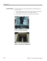
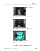
Follow Figures 1--10 through 1--14 starting on page 1--16 to repackage the
probe head and preprocessor unit.

3.

If you are shipping a probe adapter to a Tektronix service center for warranty
service, attach a tag to the probe adapter showing the following:

H

Owner’s name and address

H

Name of a person who can be contacted

H

probe adapter type and serial number

H

Description of the problem

Summary of Contents for TMSST1

Page 1: ...Instruction Manual TMSST1 775 Pin Socket Hardware Support 071 1315 00 www tektronix com ...

Page 2: ... and foreign patents issued and pending Information in this publication supercedes that in all previously published material Specifications and price change privileges reserved Tektronix Inc P O Box 500 Beaverton OR 97077 TEKTRONIX and TEK are registered trademarks of Tektronix Inc ...

Page 3: ... locations This warranty shall not apply to any defect failure or damage caused by improper use or improper or inadequate maintenance and care Tektronix shall not be obligated to furnish service under this warranty a to repair damage resulting from attempts by personnel other than Tektronix representatives to install repair or service the product b to repair damage resulting from improper use or c...

Page 4: ......

Page 5: ...1 3 Disabling the Cache 1 4 Connecting the Logic Analyzer to a Target System 1 4 Tools 1 4 Removing the Probe Head from the Target System 1 8 Applying LAI Labels 1 9 Connect the Probes and LAI Cables 1 10 P6860 Probes Four Modules 1 12 Fifth Module 1 12 Applying and Removing Power 1 12 Logic Analyzer Software Compatibility 1 13 Installing the Software 1 13 Care and Maintenance 1 14 External Cleani...

Page 6: ...ence Reference Tables 3 1 Viewing Reference Tables 3 1 To View a Symbol Table 3 1 To Extract Groups 3 1 Overview of Reference Tables 3 2 Group Definitions 3 2 Symbols 3 2 Channel Assignments 3 2 Replaceable Parts List Parts Ordering Information 4 1 Using the Replaceable Parts List 4 2 Index ...

Page 7: ...s 1 16 Figure 1 11 Place foam in the cardboard carton 1 16 Figure 1 12 Place the preprocessor unit in the cardboard carton 1 17 Figure 1 13 Place the cables carefully over the preprocessor unit 1 17 Figure 1 14 Place the foam and probe head in place 1 17 Figure 2 1 Electrical load model for typical signals 2 3 Figure 2 2 Mated Samtec load model 2 4 Figure 2 3 Receiver load model 2 4 Figure 2 4 Dim...

Page 8: ...Table of Contents iv TMSST1 775 Pin Socket Hardware Support ...

Page 9: ...cted to earth ground Before making connections to the input or output terminals of the product ensure that the product is properly grounded Observe All Terminal Ratings To avoid fire or shock hazard observe all ratings and markings on the product Consult the product manual for further ratings information before making connections to the product Connect the ground lead of the probe to earth ground ...

Page 10: ...sult in damage to this product or other property Terms on the Product These terms may appear on the product DANGER indicates an injury hazard immediately accessible as you read the marking WARNING indicates an injury hazard not immediately accessible as you read the marking CAUTION indicates a hazard to property including the product Symbols on the Product The following symbols may appear on the p...

Page 11: ... product unless another person capable of rendering first aid and resuscitation is present Disconnect Power To avoid electric shock switch off the instrument power then disconnect the power cord from the mains power Use Care When Servicing With Power On Dangerous voltages or currents may exist in this product Disconnect power remove battery if applicable and disconnect test leads before removing p...

Page 12: ...Service Safety Summary viii TMSST1 775 Pin Socket Hardware Support ...

Page 13: ...familiar with operating Microprocessor support products you need to supplement this instruction manual with information on basic operations from the Tektronix logic analyzer online help to set up and run the support product Manual Conventions This manual uses the following conventions H The terms master and slave refer to modules that are located in specific slots in a five wide module chassis see...

Page 14: ...m Sales support 1 800 833 9200 select option 1 Service support 1 800 833 9200 select option 2 Technical support www tektronix com support 1 800 833 9200 select option 3 6 00 a m 5 00 p m Pacific Standard Time This phone number is toll free in North America After office hours please leave a voice mail message Outside North America contact a Tektronix sales office or distributor see the Tektronix we...

Page 15: ...Getting Started ...

Page 16: ......

Page 17: ...processor is connected to the probe adapter Signals from the Micropro cessor based system flow through the probe adapter probe cables and to the logic analyzer This software acquires signals for viewing along with timing signals Included with the TMSST1 775 Pin Socket probe adapter is the following software H PUB32G9 software acquires signals using four modules NOTE The TMSST1 probe Adapter is com...

Page 18: ...le merge Figure 1 1 shows the configuration for a 4 or 5 wide module merge You can use the TLA7AX 450 MHz logic analyzer modules and P6860 probes to connect to the TMSST1 probe adapter For more information on connecting your P6860 probes to the preprocessor unit see page 1 10 Refer to the P6810 P6860 and P6880 Logic Analyzer Probes Instruction Manual Tektronix part number 071 1059 XX for more info...

Page 19: ...rm tasks common to support products on that platform This additional information is located in the logic analyzer online help an installation manual or a user manual Review the additional information if you are unfamiliar with using support products on a logic analyzer product Review electrical environmental and mechanical specifications in the Specifica tions section on page 2 1 as they pertain t...

Page 20: ...reprocessor unit There are no operator serviceable parts inside the preproces sor unit Refer servicing of internal parts in the preprocessor unit to Tektronix authorized personnel only External parts may be replaced by qualified service personnel You must allow airflow clearance for the preprocessor unit Refer to the dimensions on page 2 6 for the required clearance Following is a list of tools H ...

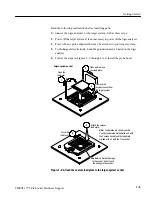
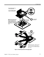
Page 21: ...connector located on the logic analyzer 4 Follow the steps in Figures 1 2 through 1 4 to install the probe head Attach the custom load plate 4 5 Close the load lever Target system socket 1 Open and remove your load plate Remove the microprocessor from the target system 3 Open the load lever 2 Caution To prevent damage to the socket do not touch the springs in the socket Note Load plates are vendor...

Page 22: ...6 Pin 1 Pin 1 7 8 Open the load lever and load plate Close load plate 10 Close the load lever 9 Probe head Caution To prevent damage to the socket do not touch the springs in the socket Caution To prevent damage to the springs in the processor socket or damage to the preprocessor unit caused by power and ground shorts check that the pin 1 s on the probe head and target system are correctly aligned...

Page 23: ...y aligned Bar Attach the probe head to the target system 11 Pin 1 12 Check the following before you connect the probe head Sthe bar is positioned as shown Syou have correctly located Pin 1 Tighten these two screws to the custom load plate torque to 8 in lbs 13 NOTE Apply forced air cooling across the microprocessor and heat sink to keep the microprocessor from overheating unless you are using a fo...

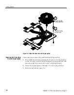
Page 24: ...ove the probe head from the target system 1 Power off the target system and unplug the AC power cord on the preproces sor unit The power switch for the probe adapter is located on the back of the preprocessor unit It is not necessary to power off the logic analyzer 2 Reverse the steps in Figures 1 2 through 1 5 to remove the probe head 3 Store the probe head see page 1 15 Removing the Probe Head f...

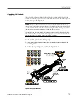
Page 25: ... always grasp it from the top right corner while removing it from the sheet of labels The adhesive on the vinyl labels is extremely strong Carefully align the label to the indented outline on the module end and preprocessor unit end Once labels are placed on the LAI cables they are difficult to remove To attach labels perform the following steps 1 Determine which channel groups you are planning to...

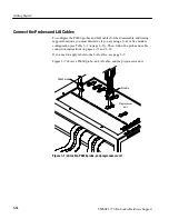
Page 26: ...st determine if you are using a four or five module configuration see Table 1 1 on page 1 11 Then follow the probe and cable connection instructions on pages 1 11 and 1 12 If you need to apply labels to the LAI cables see page 1 9 Figure 1 7 shows a P6860 probe an LAI cable and the preprocessor unit P6860 probe LAI cable Preprocessor unit Figure 1 7 LAI cable P6860 probe and preprocessor unit ...

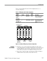
Page 27: ... signals Plus auxiliary common clock signals M A S T E R S L A V E 2 S L A V E 4 S L A V E 1 S L A V E 3 LAI cables 6 cables P6860 probes 4 probes One LAI cable and one P6860 probe Figure 1 8 LAI cable P6860 probe and module configurations 1 Match the A D C and E LAI cables from the Master module with the corresponding D3 D2 and A3 A2 D1 D0 and A1 A0 C1 C0 and C3 C2 and M_E3 E2 and E1 E0 connector...

Page 28: ...els on the preprocessor unit NOTE For more detailed information about how to attach a P6860 probe refer to the probe manual information listed on page 1 2 Applying and Removing Power To apply power to the probe adapter and target system follow these steps 1 Make sure the power switch on the preprocessor unit is in the off position If powered off the zero 0 is visible on the power switch 2 Plug the...

Page 29: ...p or the user manual NOTE Before you install any software it is recommended you verify that the microprocessor support software is compatible with the logic analyzer software To install the software on your Tektronix logic analyzer follow these steps 1 Insert the disc in the disc drive 2 Click the Windows Start button point to Settings and click Control Panel 3 In the Control Panel window double c...

Page 30: ...riginal shipping bags and cardboard carton Clean dirt and dust with a soft bristle brush For more extensive cleaning use only a damp cloth moistened with deionized water do not use any other chemical cleaning agents WARNING To prevent harm to yourself or damage to the preprocessor unit do not open the preprocessor unit for cleaning and do not allow any moisture inside the preprocessor unit There a...

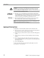
Page 31: ... not necessary to power off the logic analyzer CAUTION To prevent damage to the probe head or microprocessor use the provided extraction tool and follow the procedure from the extraction tool vendor to remove the microprocessor from the probe head 2 Reverse the steps in Figures 1 2 through 1 5 to remove the probe head CAUTION To prevent damage to the sensitive probe head cables you must dress the ...

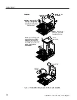
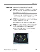
Page 32: ...ng and follow these steps 1 Disconnect the preprocessor unit from the logic analyzer by removing the probes and LAI cables from the top of the preprocessor unit 2 Follow Figures 1 10 through 1 14 to repackage the probe adapter Figure 1 10 Use static shielding bags Figure 1 11 Place foam in the cardboard carton Long Term Storage ...

Page 33: ...Figure 1 12 Place the preprocessor unit in the cardboard carton Figure 1 13 Place the cables carefully over the preprocessor unit Figure 1 14 Place the foam and probe head in place 3 Place the accessory box on top of the foam 4 Close and tape the cardboard carton To ship the probe adapter Refer to Shipping the probe Adapter ...

Page 34: ... a double walled corrugated cardboard shipping carton that allows a 3 inch 7 62 cm minimum on all sides of the product 2 Follow Figures 1 10 through 1 14 starting on page 1 16 to repackage the probe head and preprocessor unit 3 If you are shipping a probe adapter to a Tektronix service center for warranty service attach a tag to the probe adapter showing the following H Owner s name and address H ...

Page 35: ...Specifications ...

Page 36: ......

Page 37: ...icroprocessor The latched signals are processed in the ASIC according to their type Following is a description of each type 4x Quad Pumped Signals These signals include D 63 00 and DBI 3 0 The ASIC latches these signals using their dedicated strobes STBP 3 0 and STBN 3 0 and then performs four way demultiplexing on these signals The ASIC also inverts the appropriate signals when the DBI 3 0 signal...

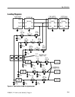
Page 38: ... signals are asserted ADS DRDY INIT RESET RS 2 0 and SNOOP_D TRACK_ERR_D This signal is asserted whenever the request or snoop counters exceed their maximum or a minimum value This signal is also asserted when ADS has been observed active for two clock cycles in a row The probe adapter uses passive series isolation to acquire data The probe adapter uses a bus tracking PAL to aid the disassembly so...

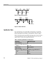
Page 39: ...ls 213 ps R1 200 Ω 15 75 Ω 25 mils 4 6 ps C1 0 7 pF C2 0 7 pF 75 Ω 44 4 18 ns 75 Ω 1350 mils 213 ps C8 0 7 pF 75 Ω 44 4 18 ns 75 Ω 1300 mils 213 ps Mated Samtec Mated Samtec Receiver Receiver 75 Ω 25 mils 4 6 ps 75 Ω 1300 mils 213 ps R2 200 Ω 15 C11 0 4 pF C6 0 7 pF C9 0 7 pF C12 0 7 pF C5 0 7 pF Coax Ribbon Loss 0 58dB 1 7GHz C3 0 7 pF 75 Ω 25 mils 4 6 ps 75 Ω 1300 mils 213 ps R3 200 Ω 15 75 Ω 44...

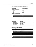
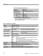
Page 40: ... in your target system must be at least 600 mVp p around the GTL reference voltage Table 2 1 lists the electrical requirements of the target system Table 2 2 lists the electrical requirements for the power supply that provides power to the probe adapter Table 2 3 lists the environmental specifications Table 2 1 Electrical specifications for the target system Characteristics Requirements Typical DC...

Page 41: ...2 2 Electrical specifications for the AC input to the preprocessor unit Characteristics Description Input Voltage rating 100 240 VAC CAT II Input Frequency Rating 50 60 Hz Input Current Rating 60 A maximum Table 2 3 Environmental specifications Characteristic1 Description Temperature Maximum operating 50 C 122 F 2 Minimum operating 0 C 32 F Nonoperating 55 C to 75 C 67 F to 167 F Humidity 10 to 90...

Page 42: ...ent Canadian Certification CAN CSA C22 2 No 1010 1 Safety requirements for electrical equipment for measurement control and laboratory use Additional Compliance IEC61010 1 A2 1995 Safety requirements for electrical equipment for measurement control and laboratory use Installation Overvoltage Category Descriptions Terminals on this product may have different installation overvoltage category design...

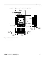
Page 43: ...e head 64 33 mm 2 533 in 35 33 mm 1 391 in 73 66 mm 2 900 in 40 36 mm 1 589 in 17 20 mm 0 677 in 1 625 mm 0 064 in 1 88 mm 0 074 in 4 57 mm 0 180 in 11 55 mm 0 455 in 1 88 mm 0 074 in Center of processor Socket pin 1 15 24 mm 0 630 in 16 86 mm 0 664 in Figure 2 4 Dimensions of the probe head Dimensions ...

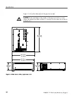
Page 44: ...CAUTION To prevent damage to the circuitry in the preprocessor unit you must observe the required clearances in Table 2 3 on page 2 6 clearances are not shown in Figure 2 5 160 27 mm 6 310 in 420 37 mm 16 550 in 139 70 mm 5 500 in 474 32 mm 18 674 in 425 45 mm 16 750 in Figure 2 5 Dimensions of the preprocessor unit ...

Page 45: ...Reference ...

Page 46: ......

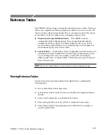
Page 47: ...efer to these tables H Symbol Tables Symbol files are files of alphanumeric symbol names and associated data values Symbol files are used to map a channel group value to a text string and or color For example a symbol file could map an address group value to a function name This is faster and easier to interpret than a numeric value NOTE The Color symbol table is not associated with any channel gr...

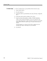
Page 48: ...under Group Name select a group 5 Open File Export Channel Setup to display a Channel Setup Export window Notice the Export Path name to locate your exported file later In the Channel Setup Export window under Export Selections check that the Export Channel Information and the Export Group Information boxes are checked The Field delimiter box controls how the tables are displayed See the Tektronix...

Page 49: ...Replaceable Parts List ...

Page 50: ......

Page 51: ...replaced with a different or improved part your local Tektronix field office or representative will contact you concerning any change in part number Modules can be serviced by selecting one of the following three options Contact your local Tektronix service center or representative for repair assistance Module Exchange In some cases you may exchange your module for a reman ufactured module These m...

Page 52: ...he serial number at which the part was first effective Column four indicates the serial number at which the part was discontinued No entry indicates the part is good for all serial numbers 5 Qty This indicates the quantity of parts used 6 Name description An item name is separated from the description by a colon Because of space limitations an item name may sometimes appear as incomplete Use the U...

Page 53: ...CORD MFG CO INC 312 EAST MAIN STREET WESTFIELD PA 16950 0KB01 STAUFFER SUPPLY CO 810 SE SHERMAN PORTLAND OR 97214 4657 1K3Q9 PACKAGING RESOURCES 12555 SW TUALATIN SHERWOOD RD TUALATIN OR 97062 8051 1WNW6 ACCRA FAB INC 23201 E APPLEWAY LIBERTY LAKE WA 99019 S3109 FELLER U S CORPORATION 10B VAN DYKE AVENUE NEW BRUNSWICK NJ 08901 TK1373 PATELEC CEM 10156 TORINO VAICENTALLO 62 456 ITALY TK6121 TUMBLER...

Page 54: ... STORAGE PLASTIC W FOAM 12 4X8 9X2 9 FLEX CABLE ASSEMBLY 1K3Q9 016194000 STANDARD ACCESSORIES 071 1315 XX 1 MANUAL TECH INSTRUCTION HARDWARE SOFTWARE PUB 32G9 TMSST1 TK2548 071 1315 XX 161 0104 00 1 CABLE ASSY PWR 3 18 AWG 98 0 L 125V 10AMP RIGHT ANGLE IEC320 NEMA 15 5P WITH CORD GRIP US SAFETY CONTROLLED TK6121 3572WV88 2GI 10 012 1661 00 6 7 CA ASSY INTCON SHLD RIBBON MCP 72 L 060D9 012 1661 00 ...

Page 55: ...Replaceable Parts List TMSST1 775 Pin Socket Hardware Support 4 5 1 2 3 4 5 6 7 8 9 10 Figure 4 1 Probe adapter exploded view ...

Page 56: ...Replaceable Parts List 4 6 TMSST1 775 Pin Socket Hardware Support ...

Page 57: ...Index ...

Page 58: ......

Page 59: ...he cache 1 4 Disassembler logic analyzer configuration 1 1 setup 1 13 E Electrical specifications 2 1 2 4 AC adapter 2 5 clock rate 2 4 power requirements 2 4 setup time 2 4 source synchronous capture disabled 2 5 Environmental specifications 2 5 airflow clearance 2 6 altitude 2 5 electrostatic immunity 2 6 humidity 2 5 temperature 2 5 F Fuses maintenance 1 14 G Group definitions 3 2 I Installing ...

Page 60: ...get system 1 8 1 15 Reset 1 3 Restrictions 1 3 address bus 1 3 clock rate 1 3 data bus 1 3 disabling the cache 1 4 S Service support contact information x Setups disassembler 1 13 support 1 13 Shipping probe adapter assembled 1 18 Slave module definition ix Specifications 2 1 electrical 2 1 2 4 environmental 2 5 mechanical dimensions 2 8 2 9 Storage long term 1 16 Support setup 1 13 Symbol tables ...

Reviews: