


Pulse Pro
fi
ling Application
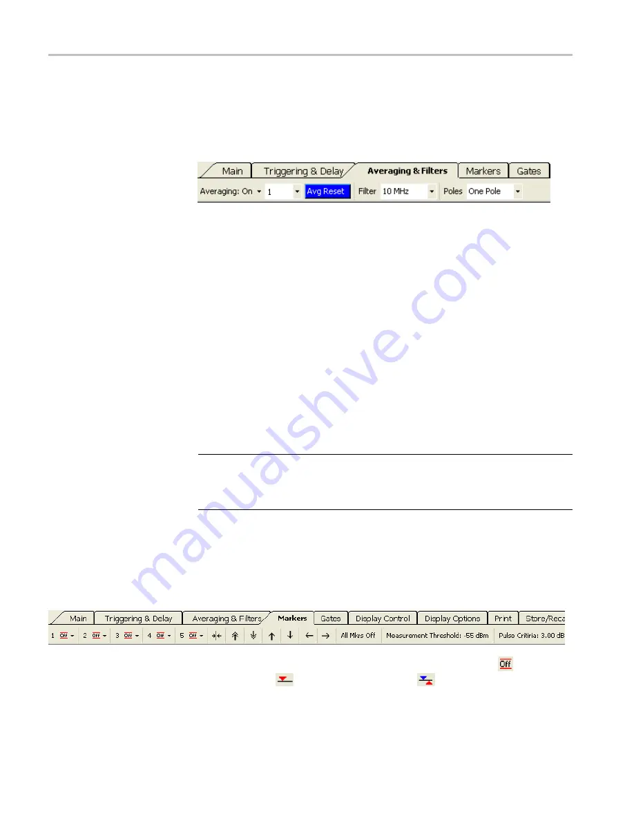
Averaging & Filters
You can use averaging and the low-pass
fi
lter can help improve measurements
near the noise
fl
oor of the instrument. Increasing the number of averages
maintains wave shape but slows down the update rate of the trace. A lower
low-pass
fi
lter setting will provide faster trace updates, but results in a rounded
pulse shape with longer rise and fall times.
Averaging.
Select to turn averaging on or off. When this function is turned on,
you can select the number of traces to be averaged from the drop down menu. The
number of averages can be set from 1 to 100. It takes 0.3 to 1.0 ms to collect
each trace.
Average Reset.
This button is blue when averaging is turned on. Click the button
to restart or reset trace averaging.
Filter.
This function allows you to select an appropriate low-pass video
fi
lter
depending on your measurement needs. You can choose 100 kHz, 200 kHz,
300 kHz, 500 kHz, 1 MHz, 2 MHz, 3 MHz, 5 MHz, and 10 MHz. (The 10 MHz
setting is equivalent to turning the
fi
lter function off.)
Poles.
This menu selection allows you to choose from one, two, three, or four
poles. The number of poles determines the roll off rate of the low pass video
fi
lter.
The greater the number of poles, the steeper the roll off, resulting in a reduction in
the high frequency components of the signal.
NOTE.
An informational dialog box will appear if the measurement becomes
uncalibrated due to
fi
lter, poles, or sweep time settings. An “Uncal Meas” label
will also appear on both the Panoramic Trace and Measurement Trace grids.
Adjust the settings accordingly until the error message stops.
Markers
Markers are used to make measurements at a particular point (Normal Markers) or
measure the difference between two points (Delta Markers). Markers are only
available in the Measurement Trace window. The value of the active marker is
displayed in the upper left portion of the Measurement Trace window unless it is
turned off. The value of each marker is displayed in the Results window.
Marker 1 through 5.
Select the marker numbers to turn them off (
), on as a
Normal marker (
), or on as a Delta marker (
). You can then select
Set
Position
from each marker drop down menu to position the marker. You can also
place the marker by clicking in the Panoramic Trace window.
40
RF and Microwave Power Sensors/Meters
Summary of Contents for PSM3000 Series
Page 2: ......
Page 6: ......
Page 10: ...Table of Contents iv RF and Microwave Power Sensors Meters...
Page 14: ...Preface viii RF and Microwave Power Sensors Meters...
Page 26: ...Getting Started 12 RF and Microwave Power Sensors Meters...
Page 32: ...Operating Basics 18 RF and Microwave Power Sensors Meters...
Page 74: ...High Speed Logger Application 60 RF and Microwave Power Sensors Meters...


